

CAD Guides: STEP Measurement, Weight & File Formats
Practical notes on CAD formats, model properties, units and engineering handoffs. — Page 6
Engineering guides
61–64 of 64 results
 Troubleshooting
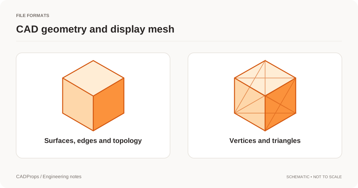
STL Volume Zero or Missing? Check the Mesh Is Closed
Diagnose STL files with zero, missing or unreliable volume by checking watertightness, inconsistent faces, units and export quality before calculating mass.
More →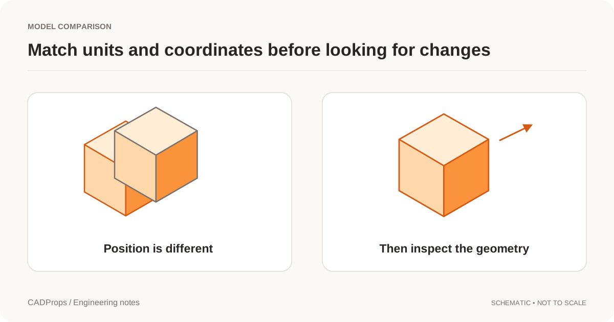 Versions & review
CAD Versions vs Revisions: Track Models and Exports
Keep upload history, engineering revision labels and converted files separate so a new export does not masquerade as a design change.
More →Versions & reviewCompare CAD Revisions: Geometry and Property Checks
Use fixed versions, explicit units and a deliberate alignment method before interpreting overlays or property differences.
More →Versions & reviewShare a Fixed CAD Revision: File and Version Checklist
Pin a shared model or comparison to an explicit version, check recipient permissions and handle replacements without silent updates.
More →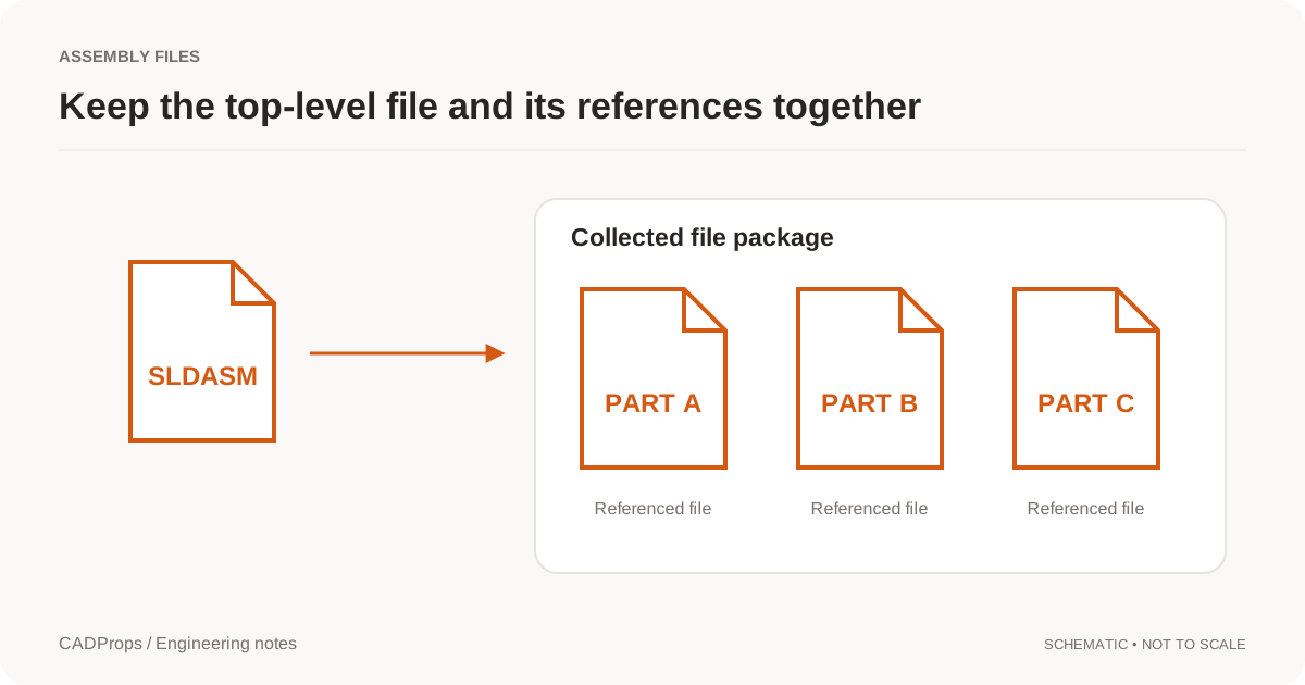 Batch & handoff
Annotate a CAD Model Online and Share Review Notes
Place numbered notes on a 3D model, return to saved viewpoints, and include saved annotations in a new CADProps share link.
More →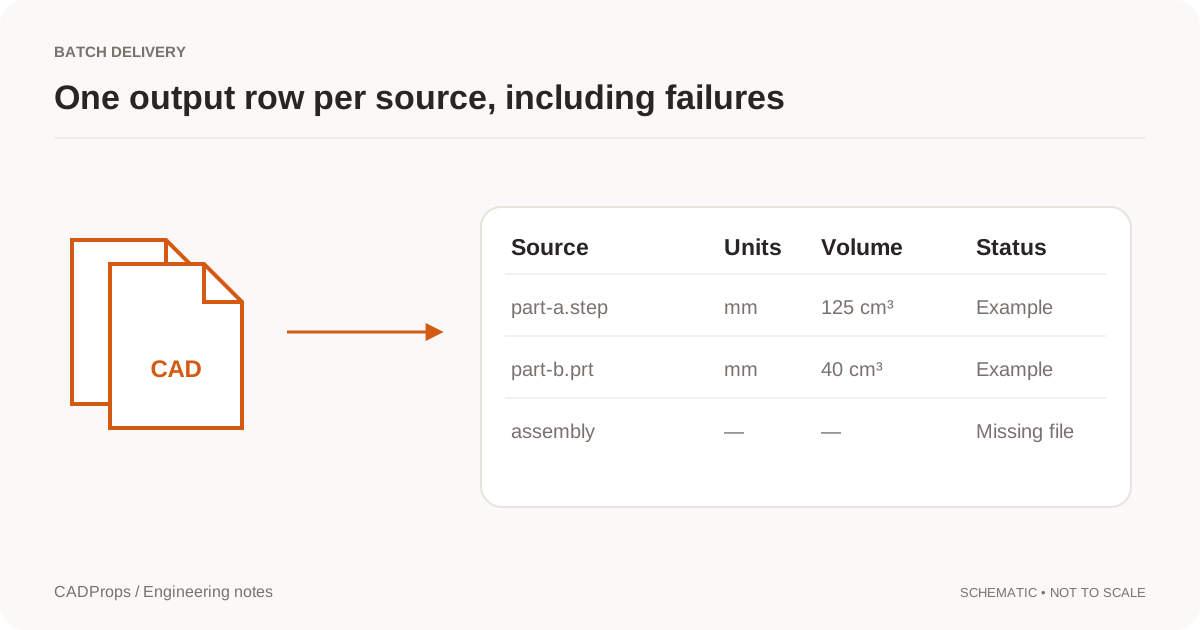 Batch & handoff
Export STEP Properties to Excel: Batch CAD Measurements
Design a useful batch report with one row per defined item, explicit units, material inputs and an exceptions list.
More →Batch & handoffPrepare a STEP File for a CNC Quote: A Shop-Ready RFQ Checklist
Check STEP geometry, units, holes, revision, drawing requirements, material and quantity before sending a CNC machining RFQ, without assuming the 3D model contains every manufacturing requirement.
More →Batch & handoffShare CAD Files with Suppliers: STEP Handoff Checklist
Prepare a small delivery package that identifies the model revision, intended use, units and any excluded components.
More →Batch & handoffThreads Missing from a STEP File? Geometry, PMI and Shop Handoffs
Understand why thread callouts can disappear in STEP handoffs, how modeled and cosmetic threads differ, what AP242 PMI can carry, and what to send a machine shop.
More →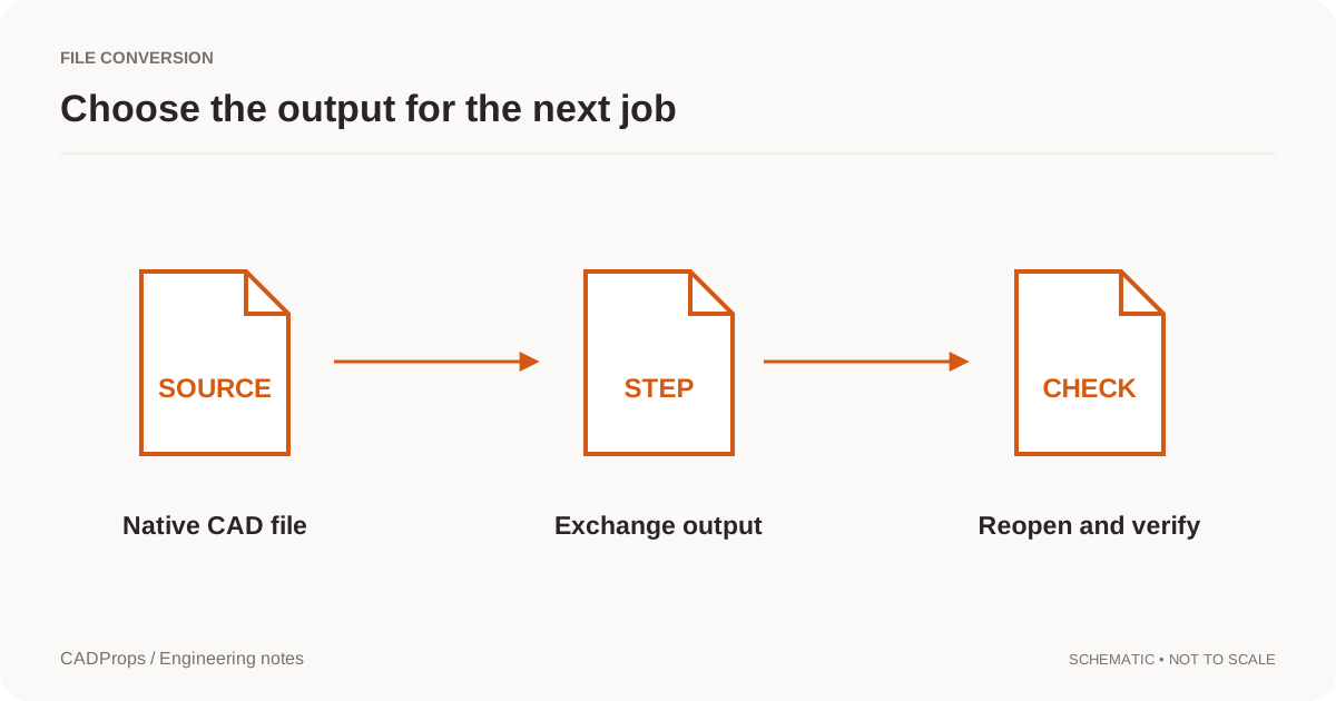 Conversion
CAD File Conversion Checklist: Units, Solids & Accuracy
Reopen the output, verify scope and units, inspect critical geometry, and include a short record of what was and was not checked.
More →ConversionHow to Convert NX PRT to STEP: Units & Assembly Checks
Convert Siemens NX or UG NX PRT files to STEP with a repeatable check for source identity, units, assemblies and the converted geometry.
More →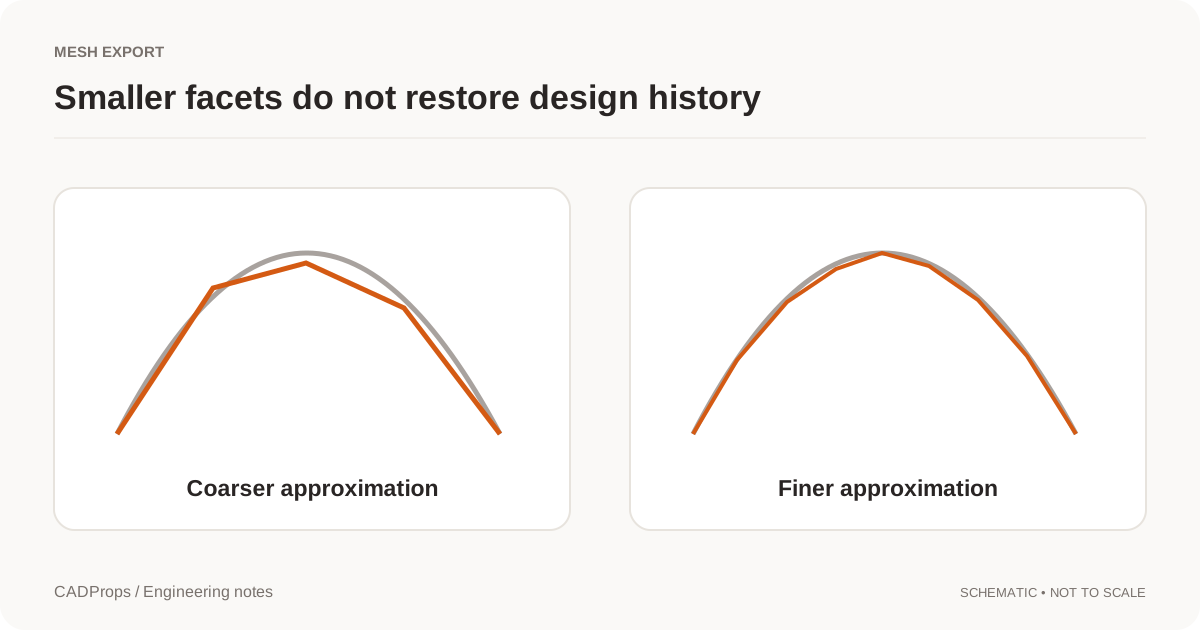 Conversion
STL Export Settings: Mesh Resolution, Units and Scale
Choose tessellation settings for the receiving task and verify curved features, thin regions and units after exporting.
More →Engineering notesAutodesk Fusion AutoTimeline: Why CAD Feature Recognition Matters Again
A CADProps engineering note on Autodesk's September 2026 AutoTimeline announcement, imported-geometry feature recognition, and why explainable geometry checks still matter as AI moves deeper into CAD and CAM.
More →File formats3MF vs STL: Units, Multiple Parts and Mesh Handoff
Compare 3MF and STL for mesh exchange, including declared units, packaging, multiple objects, metadata and what CADProps can actually inspect from each format.
More →File formatsCAD Tessellation: When a Solid Becomes a Triangle Mesh
Tessellation approximates CAD faces with triangles for display, STL or glTF. Finer meshes stay approximate and do not restore B-Rep volume.
More →File formatsGLB and glTF for CAD Handoff: A Viewing Mesh, Not the Source
Use GLB or glTF to show a CAD model. Keep STEP when the recipient must measure solids, machine the part or edit the design.
More →File formatsGLB vs glTF for CAD: 3D Model Files, Assets and Units
Use a display derivative for the web while keeping engineering geometry and revision records separate.
More →File formatsIGES vs Parasolid: Surfaces, Solids and CAD Exchange
Compare IGES and Parasolid X_T by the receiving system, solid closure and units. Neither extension guarantees a perfect transfer or a native feature tree.
More →File formatsJT vs STEP: Lightweight Collaboration or Neutral CAD Exchange?
Compare JT and STEP for visualization, precise geometry, supplier collaboration, product structure and cross-CAD exchange, including the current CADProps JT solid workflow.
More →File formatsParasolid vs STEP: CAD Geometry and Exchange Formats
Choose an exchange route by the receiving application and required data, not by assuming one file extension always converts better.
More →File formatsSAT vs IGES: ACIS Solids or Neutral CAD Surfaces
Choose SAT or IGES by the receiving application. Text SAT is ACIS geometry; IGES is a neutral exchange file. Binary SAB is not enabled.
More →File formatsSAT vs STEP: ACIS Geometry or Neutral CAD Exchange?
Compare SAT and STEP for precise solid-model exchange, ACIS compatibility, cross-CAD handoff, version risk and the current CADProps SAT-to-STEP workflow.
More →File formatsSTEP AP203 vs AP214 vs AP242: Colors and CAD Data
Understand STEP application protocols without treating the highest version number as a guarantee that every CAD reader preserves the same data.
More →File formatsSTEP AP242 Edition 4 in 2026: What It Means for CAD Handoffs
Put AP242 Edition 4 in practical context: richer model-based product data, persistent identity and PMI improvements, current 2026 implementation signals, and the checks that still matter after export.
More →File formatsWhy STEP Files Lose the SolidWorks Feature Tree
A neutral CAD export can preserve useful geometry without preserving the original feature history. Learn what to request and what not to promise.
More →File formatsSTEP vs IGES: Which CAD Exchange Format Fits the Job?
Compare STEP and IGES for CAD handoffs, solids, surfaces, assemblies and downstream verification without assuming one file extension guarantees a perfect transfer.
More →File formatsSTEP vs STL: CAD Measurement, Geometry and Accuracy
STEP and STL serve different jobs. Learn what changes when surfaces become triangles and which checks belong in a CAD handoff.
More →File formatsSTEP vs STP Files: Extensions and CAD Compatibility
STEP and STP are common extensions for the same exchange format. Learn what renaming changes, what it does not, and which checks matter more.
More →File formatsWhat B-Rep Means in a STEP or IGES File
Boundary representation is the face, edge and solid model behind precise CAD properties. A shaded triangle view is not the same thing.
More →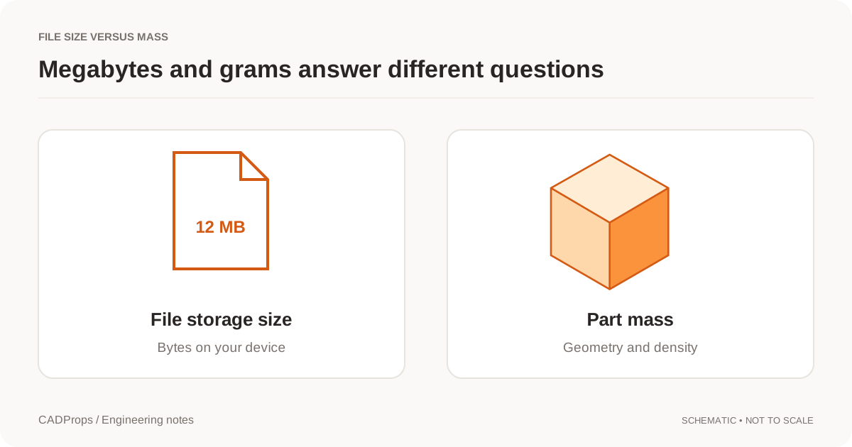 Measurement
CAD File Size vs Part Weight: Why MB Does Not Mean Mass
Megabytes describe storage. Grams describe mass. Here is why a large file can represent a light part, and what you need for a useful mass estimate.
More →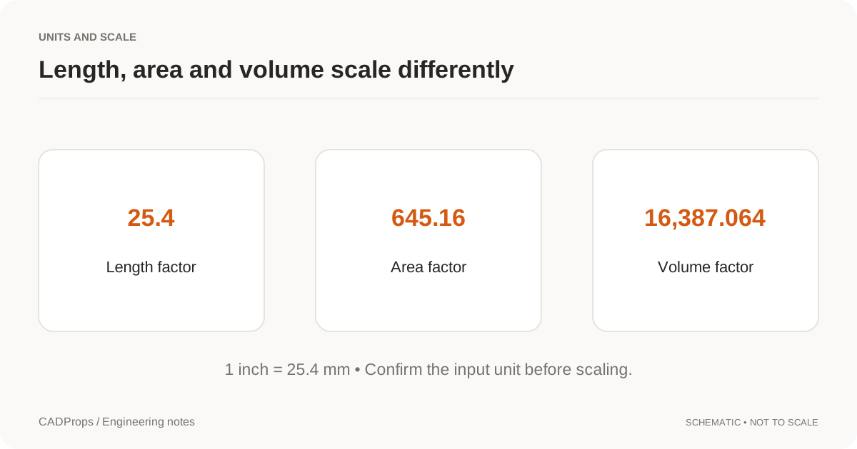 Measurement
STEP File Scale Wrong by 25.4? Fix Inch and mm Units
Diagnose STEP and CAD models that import 25.4× too large or small by checking inch/mm interpretation, a known dimension and downstream import settings.
More →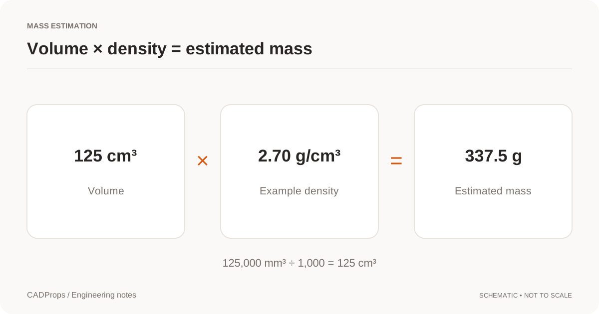 Measurement
How to Calculate Volume from a STEP File
Calculate volume from a STEP file using valid CAD solid geometry, verify units and body scope, diagnose unavailable results, and use volume safely for mass estimates.
More →MeasurementCalculate STEP File Weight from Volume and Density
Work from valid solid volume, choose a documented density and keep units, configuration and assembly scope visible in the result.
More →MeasurementMeasure STEP Files Online: Dimensions, Distances & Units
Measure STEP files online, check X/Y/Z dimensions, verify units, distinguish bounding boxes from local measurements, and record the geometry scope correctly.
More →MeasurementOBJ Mesh Units and Volume: Check Scale and a Closed Shell
OBJ does not declare reliable units. See how millimetres are assumed, when mesh volume is only an approximation, and why OBJ is not a CAD solid.
More →MeasurementSTEP File Bounding Box: Get Overall Dimensions Online
Read a STEP file's overall X, Y and Z extents, understand why orientation changes a bounding box, and avoid confusing envelope dimensions with drawing dimensions.
More →MeasurementSTEP Hole Recognition: Detect Through and Blind Holes
Recognize supported cylindrical holes in STEP files, read diameter and depth from B-Rep geometry, and understand why stepped, intersecting or conical holes remain unclassified.
More →MeasurementDo STL Files Have Units? How to Fix mm vs Inch Scale
Understand why STL coordinates do not reliably declare physical units, diagnose mm-versus-inch scale errors, and verify dimensions before printing or manufacturing.
More →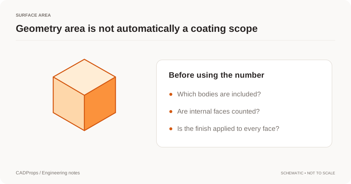 Measurement
Calculate Surface Area from a STEP File
Calculate STEP file surface area from CAD faces, verify units and body scope, distinguish total geometry from process area, and avoid common coating-estimate mistakes.
More →Opening filesOpen a Rhino 3DM File Without Rhino
3DM is not an enabled upload format. Ask for STEP, IGES or STL from Rhino, then check units and whether the export is a solid or a mesh.
More →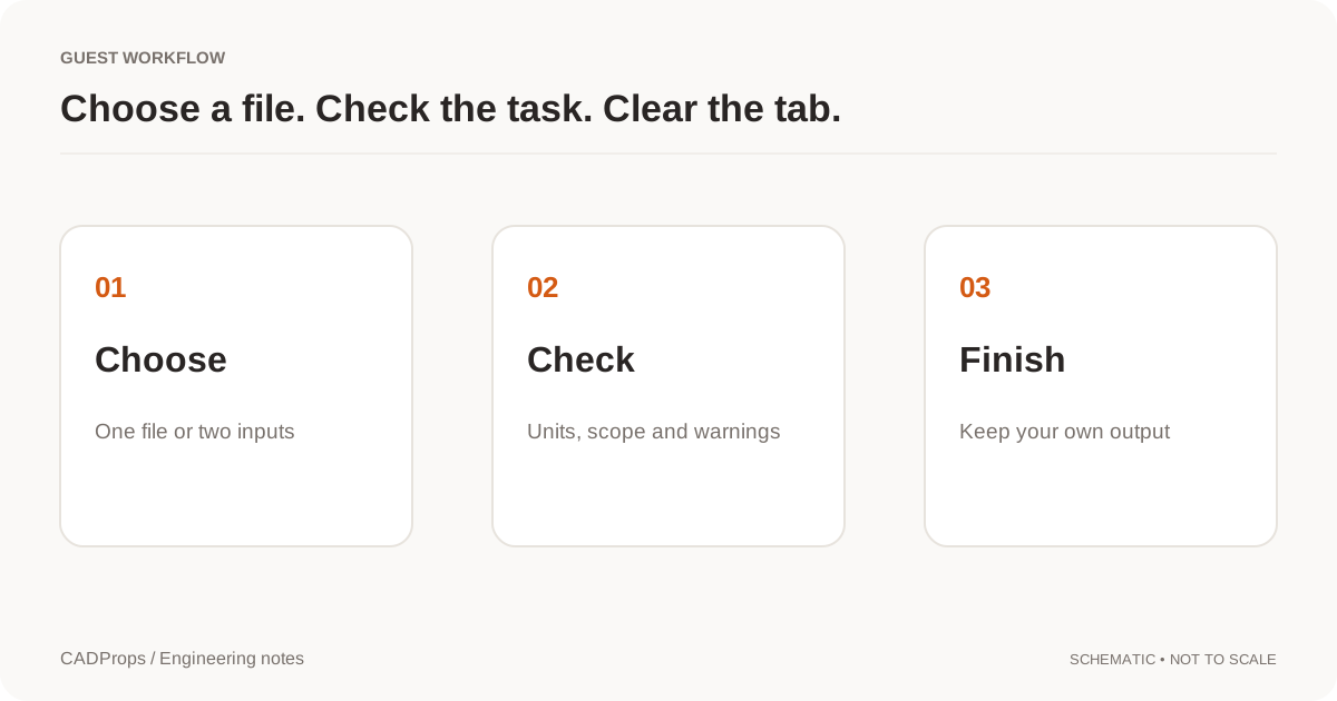 Opening files
Open CAD Files on Mac: STEP Viewers and Format Options
A practical Mac workflow for STEP, SLDPRT and NX PRT files: identify the format, check browser or desktop options, and verify the result.
More →Opening filesHow to Open a CATPart File Without CATIA
Open CATIA V5 CATPart files without CATIA, verify version, geometry and units, package CATProduct dependencies, and convert readable models to STEP when needed.
More →Opening filesHow to Open a CATProduct File Without CATIA
Open CATIA V5 CATProduct assemblies without CATIA by packaging referenced CATPart files, checking missing components, verifying dimensions and converting to STEP.
More →Opening filesOpen a Creo File Without Creo
Creo PRT and ASM files are not opened by the Siemens NX path. Identify the source, ask for STEP, and do not rename a Creo file to force a reader.
More →Opening filesOpen DWG or DXF Files Without AutoCAD
DWG and DXF are not enabled for viewing or conversion. 2D drawings are not supported. For 3D geometry, ask for a self-contained STEP file.
More →Opening filesHow to Open an IAM File Without Autodesk Inventor
Open Autodesk Inventor IAM assemblies without Inventor by packaging referenced IPT files, checking missing components, verifying dimensions and converting to STEP.
More →Opening filesHow to Open an IPT File Without Autodesk Inventor
Open Autodesk Inventor IPT files without Inventor, verify geometry and units, handle IAM assembly references, and convert supported models to STEP when needed.
More →Opening filesHow to Open JT Files Online and Check Solid Geometry
Open a JT file in a browser, verify readable solids, dimensions and properties, understand JT geometry limits, and validate a STEP handoff.
More →Opening filesHow to Open an NX PRT File Without Siemens NX
Open Siemens NX or UG NX PRT files without installing NX, identify ambiguous PRT sources, package assembly references, verify dimensions and convert to STEP when needed.
More →Opening filesHow to Open SAT Files Online Without an ACIS CAD System
Open an ACIS SAT file in a browser, verify solids, units and dimensions, understand SAT versus SAB, and validate a STEP handoff before reuse.
More →Opening filesHow to Open an SLDASM File Without SolidWorks
Open SolidWorks SLDASM assemblies without SolidWorks by packaging referenced SLDPRT files, checking missing components, verifying dimensions and converting to STEP.
More →Opening filesHow to Open an SLDPRT File Without SolidWorks
Open SolidWorks SLDPRT files without SolidWorks, verify the source version and geometry, measure the part, and convert supported models to STEP when needed.
More →Opening filesOpen a Solid Edge File Without Solid Edge
Solid Edge PAR, PSM and ASM files are not opened here. Ask for STEP or Parasolid X_T, then verify units, scope and closure before using properties.
More →Opening filesHow to Open an X_T File Online Without Parasolid Software
Open Parasolid X_T files online, verify the source model and units, measure readable geometry, and know when to convert the file to STEP.
More →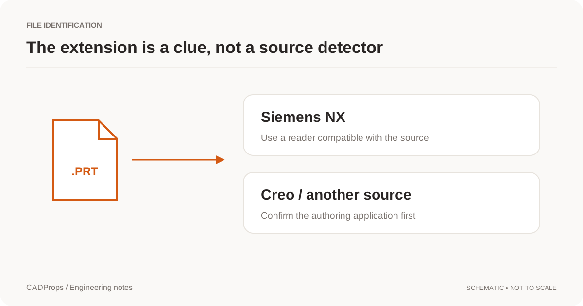 Opening files
NX or Creo PRT File? Identify the CAD Format
PRT does not uniquely identify Siemens NX. Check the sender, application version, dependencies and reader before attempting a conversion.
More →Opening filesPack a CAD Assembly ZIP: Choose the Root and Keep Paths
Package an assembly with its referenced parts, keep relative folders, and choose the root model so missing components are visible instead of silent.
More →TroubleshootingCATProduct Missing Parts? Fix CATIA Assembly References
Diagnose CATIA CATProduct assemblies with missing CATPart components, preserve folder structure, rebuild the package and avoid incomplete geometry or STEP exports.
More →TroubleshootingglTF Missing Textures? Fix .bin and Image File Paths
Diagnose glTF files that open with missing geometry resources or textures, package relative .bin and image dependencies correctly, and know what CADProps does and does not render.
More →TroubleshootingIAM Missing Parts? Fix Autodesk Inventor Assembly References
Diagnose Inventor IAM assemblies with missing IPT or nested IAM components, preserve folder structure, rebuild the package and avoid incomplete geometry totals.
More →TroubleshootingIGES Surfaces Not Solid? Check Volume and Open Shells
Understand an IGES surface import before stitching boundaries or assuming the reader failed to create a solid.
More →TroubleshootingSLDASM Missing Parts? Fix SolidWorks Assembly References
Diagnose SolidWorks SLDASM assemblies with missing SLDPRT components, preserve folder structure, distinguish partial geometry from complete results, and rebuild the package.
More →TroubleshootingReduce STEP File Size: Keep Required CAD Geometry
Distinguish archive compression, model simplification and display optimization before changing a CAD handoff.
More →TroubleshootingWatertight Mesh: When an STL Can Have a Volume
A watertight mesh is a closed, consistent triangle boundary. Open or inconsistent STL and OBJ meshes have no reliable volume, and CADProps does not replace that with zero.
More →TroubleshootingSTEP File Volume Zero or Missing? Check Solid Geometry
Diagnose STEP files that show zero or unavailable volume by checking open shells, solid closure, selected scope, units, missing components and geometry-processing warnings.
More →TroubleshootingSTL Volume Zero or Missing? Check the Mesh Is Closed
Diagnose STL files with zero, missing or unreliable volume by checking watertightness, inconsistent faces, units and export quality before calculating mass.
More →Versions & reviewCAD Versions vs Revisions: Track Models and Exports
Keep upload history, engineering revision labels and converted files separate so a new export does not masquerade as a design change.
More →Versions & reviewCompare CAD Revisions: Geometry and Property Checks
Use fixed versions, explicit units and a deliberate alignment method before interpreting overlays or property differences.
More →Versions & reviewShare a Fixed CAD Revision: File and Version Checklist
Pin a shared model or comparison to an explicit version, check recipient permissions and handle replacements without silent updates.
More →