

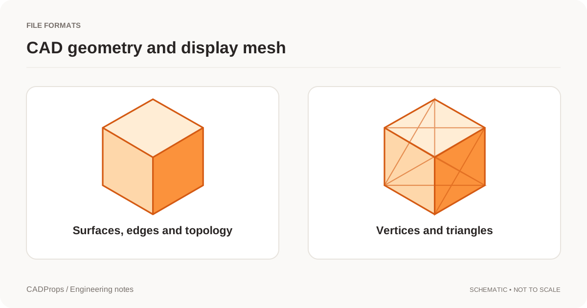
B-Rep, short for boundary representation, describes a solid or a surface by its boundaries: faces, edges and vertices, with the geometry of those faces. A cylinder can be a true cylindrical face rather than a ring of flat triangles. STEP and IGES readers on this site use that kind of model when the file contains it.
The picture in the browser is usually a triangle mesh generated so the shape can be drawn. That display mesh is not the B-Rep. Measuring a precise edge or a cylindrical diameter, when the tool supports it, uses the CAD geometry. A point-to-point pick on the shaded mesh is only as good as the triangles.
What B-Rep is used for here
| Property | What it requires |
|---|---|
| Dimensions of analytic faces and edges | Readable B-Rep geometry, plus a confirmed unit scale |
| Surface area | The selected faces. Open shells can still have area |
| Solid volume | A valid closed solid with consistent orientation |
| Mass | That volume, times a density you supply |
| Hole labels | Geometric classification of supported simple holes, not a feature tree |
Open CASCADE documents the closure and orientation assumptions behind volume properties. BRepGProp documentation. If those assumptions fail, the volume is unavailable. It is not reported as zero so that a later spreadsheet looks complete.
B-Rep is not a feature tree
A STEP file can carry accurate B-Rep and still have no sketches, constraints or ordered features from SolidWorks, Inventor, CATIA, NX or any other authoring system. You can measure the solid without being able to edit the original design history. STEP vs STL makes the same distinction from the mesh side: converting triangles back into a STEP file can wrap planar faces, but it does not recover the surfaces that existed before tessellation.
IGES is not "non-B-Rep" by definition. A particular IGES file may be a set of untrimmed or unjoined surfaces. Those surfaces can be inspected for area and still fail a solid-volume check. See IGES surfaces that are not solids.
How to tell which representation you are using
- Open the STEP or IGES file and confirm the expected bodies loaded.
- Check one known dimension. The unit interpretation belongs to the B-Rep scale, not to the zoom level.
- Prefer CAD face and edge measurements for engineering features.
- If volume is missing, read the status before you change the model. The diagnostic order is in STEP volume zero.
- If you export STL, OBJ, 3MF or glTF, label later numbers as mesh results. Tessellation is the step that creates those triangles.
A bounding box is neither the B-Rep volume nor a drawing dimension. It is the axis-aligned extent of whatever geometry was included.
Original article: CADProps · https://www.cadprops.com/guides/what-is-brep/