

STEP and IGES are both neutral CAD exchange formats, but they are not interchangeable promises about what a receiving system will get.
For many modern mechanical handoffs, STEP is the more common starting point because it can carry structured product geometry and assembly information. IGES remains relevant in legacy environments and surface-oriented workflows. The correct choice still depends on the source data, exporter, recipient and information that must survive the transfer.
If you have already received a file, you can inspect it with the STEP viewer or IGES viewer. If you are choosing what to send, define the downstream requirement before choosing the extension.
STEP and IGES solve the same broad problem
Native CAD formats are tied to particular authoring systems and versions. Neutral exchange formats provide a way to move geometry between different applications.
IGES predates STEP and is widely associated with exchange of curves, surfaces and other geometric entities.
STEP is part of the ISO 10303 family and is designed for exchange of product-model information. Depending on the application protocol and implementation, that can include geometry, product structure and other associated information.
NIST's STEP resources describe STEP as more than a single geometry container and provide tools for analyzing file structure and product data. NIST STEP reference.
The practical lesson is simple: compare what your workflow needs, not only the file extension.
Do not reduce the comparison to "surfaces versus solids"
A common shortcut says:
IGES is surfaces; STEP is solids.
That is too simple.
An IGES file can contain geometry that imports cleanly and is perfectly useful for its intended workflow. A STEP file can also arrive with geometry that is incomplete, unsuitable for a specific downstream task or represented differently than expected.
Likewise, a successful shaded preview does not prove that a model imported as a valid manufacturing solid.
The useful questions are:
- Did the intended faces and bodies arrive?
- Is the geometry closed where a solid is required?
- Are units correct?
- Is assembly organization needed?
- Are names, colors or other attributes important?
- Does the receiving application actually support the data written by the exporter?
Format choice is only one part of that chain.
Where STEP is usually a strong choice
STEP is often a good starting point when the receiver needs a mechanical CAD handoff across different systems.
Typical reasons include:
- exchanging B-Rep part geometry,
- carrying multiple bodies or product structure,
- preserving placements in supported assemblies,
- using a neutral format accepted by many CAD/CAM systems,
- supporting workflows that depend on specific STEP application protocols.
For modern supplier handoffs, a sender may choose STEP because the recipient already has a tested STEP import path.
That does not mean every STEP export preserves the original native feature tree. A neutral model can contain accurate geometry without retaining editable sketches, constraints and feature history from the source CAD system.
Where IGES still makes sense
IGES remains useful when the receiving workflow explicitly requires it or when established legacy tooling has a known, tested IGES path.
It can also appear in workflows centered on curves and surfaces rather than complete solid product structure.
The key is to distinguish a deliberate surface workflow from an accidental open-shell result.
CADProps can report dimensions and surface area for readable IGES surfaces even when a reliable closed-solid volume is not available. The IGES surfaces guide explains why a model can look complete on screen but still fail a solid-volume calculation.
Do not convert a valid IGES workflow to STEP merely because STEP is newer if the actual receiving process has been qualified around IGES.
Assembly structure can change the decision
When exchanging an assembly, geometry alone may not be enough.
Ask whether the recipient needs:
- component hierarchy,
- repeated instances,
- part names,
- placements,
- colors,
- separate component identities.
A flattened geometric result might look correct while losing the structure needed for BOM review, component selection or downstream automation.
If assembly organization matters, test it explicitly in the target software.
Do not infer support from a checkbox labelled "STEP" or "IGES." Reader and writer capabilities can differ, and support can vary by file version and data category.
Surface quality and "healing" should be verified, not assumed
Translation between CAD systems can expose small gaps, trimming differences or topology problems.
An importer may offer sewing or healing operations. Those can be useful, but a repaired result is a changed interpretation of the source data and should be checked.
For a critical part, compare:
- overall dimensions,
- body count,
- known cylinders and holes,
- mating faces,
- internal pockets,
- expected open or closed regions.
If the receiver needs a closed solid and an IGES import produces open shells, requesting a cleaner export from the source system may be more defensible than progressively increasing repair tolerances.
STEP application protocol matters too
Choosing STEP does not end the format decision.
AP203, AP214 and AP242 are different STEP application-protocol families and editions. Exporter and importer support determines which portions of the data survive in practice.
If color, product structure or PMI-related information matters, state that requirement directly.
The AP203/AP214/AP242 guide explains why the largest protocol number should not be treated as an automatic quality setting.
A task-based comparison
| Requirement | STEP | IGES |
|---|---|---|
| Modern neutral mechanical handoff | Common starting choice | Still usable where supported |
| Surface-focused legacy workflow | Possible, depending on data | Common in established workflows |
| Closed-solid property calculation | Works when valid solid geometry is present | Works only when imported geometry forms a valid solid |
| Assembly/product structure | Can be represented by suitable STEP data | Do not assume equivalent product structure |
| Original parametric feature history | Not guaranteed | Not guaranteed |
| Recipient-specific compatibility | Must be tested | Must be tested |
This table is a workflow guide, not a claim that every STEP or IGES file contains the listed information.
Which should you send to a machine shop?
Ask the shop.
If they request STEP and have a proven import workflow, send the requested STEP export with the correct revision and units.
If they request IGES because a qualified legacy process expects it, follow that requirement unless both sides agree to change the handoff.
For either format, include the controlling drawing or agreed specification when manufacturing requirements are not fully represented in the 3D model.
A file that opens is not automatically the approved manufacturing definition.
If you received both STEP and IGES
Do not assume they are equivalent just because the filenames share the same part number.
Check:
- source revision,
- export time or release context,
- units,
- body count,
- overall dimensions,
- important functional geometry.
If both files were produced from the same approved model, their geometry should be consistent within the expectations of the translators. If they differ materially, resolve the source before choosing whichever one opens more easily.
STEP versus IGES versus STL
STL is a different category of handoff.
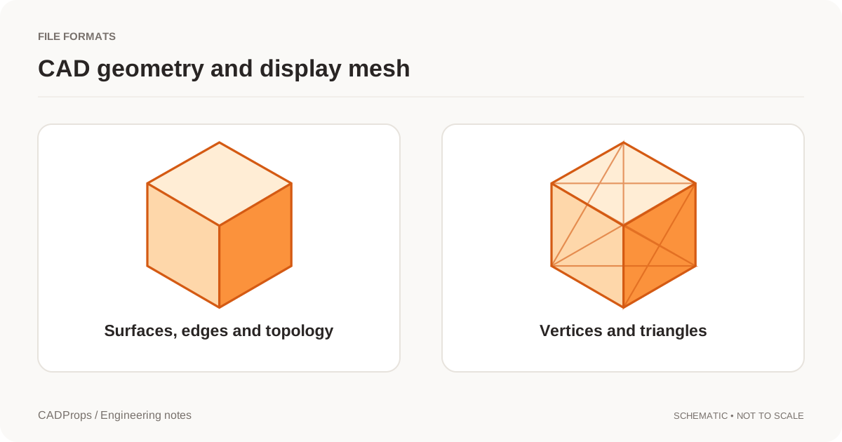
STEP and IGES can carry CAD geometry such as curves and surfaces. STL represents a triangulated surface mesh.
That distinction affects measurement, curved geometry and downstream engineering use. See STEP vs STL when the alternative being considered is a mesh rather than another neutral CAD exchange format.
Use a repeatable handoff check
Whatever format you choose, verify the result in the receiving workflow.
A practical checklist is:
- Confirm source revision and configuration.
- Confirm units.
- Open the exported file.
- Check expected bodies or components.
- Measure one known dimension.
- Inspect one or two critical features.
- Record known limitations.
The CAD conversion checklist turns those checks into a repeatable process.
The better format is the one that preserves the information your next workflow requires and has been verified in the systems actually exchanging the data.
Original article: CADProps · https://www.cadprops.com/guides/step-vs-iges/