
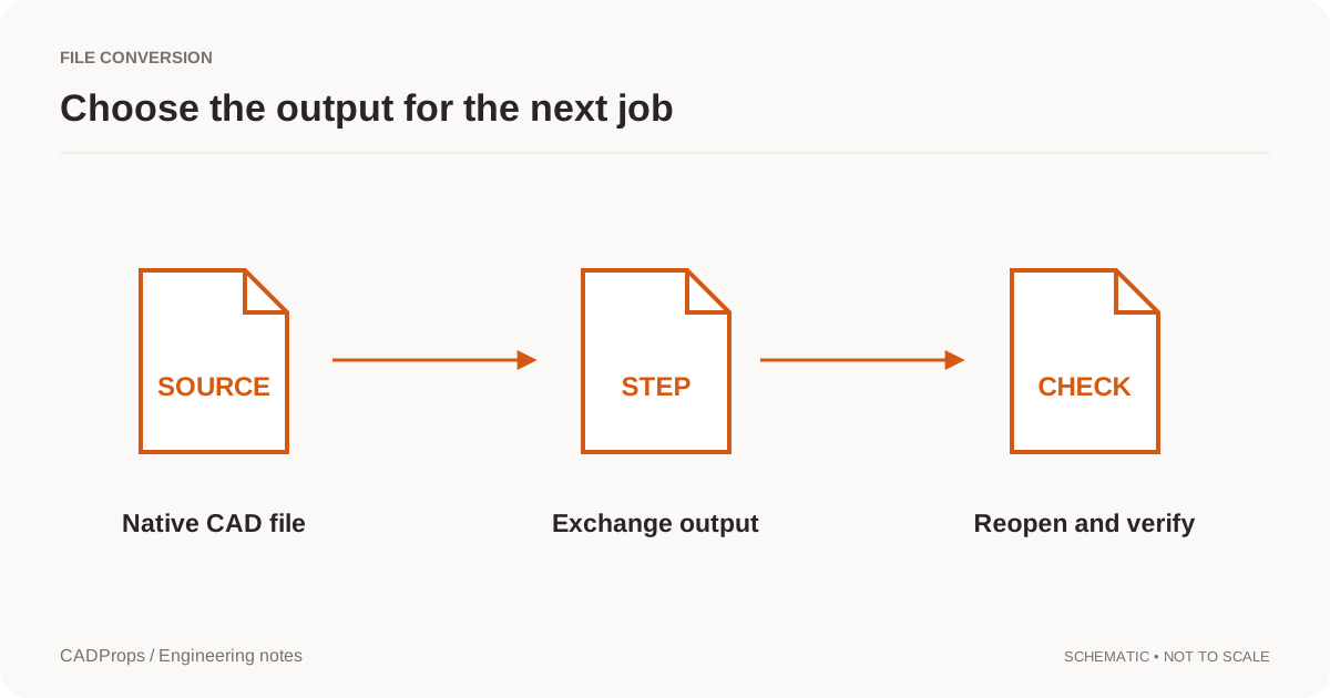
“Conversion complete” means a process reached its successful exit state. It does not necessarily mean the output meets the next person's engineering requirements. The right acceptance check starts with what the recipient needs from the file.
Use this checklist for a controlled handoff. It is a practical review procedure, not a certification scheme or a replacement for a contractual validation requirement.
1. Identify the source and the intended scope
Record the original file, revision, authoring application when known and the configuration selected for export. Identify whether the task covers one body, a part, an assembly or a selected subset.
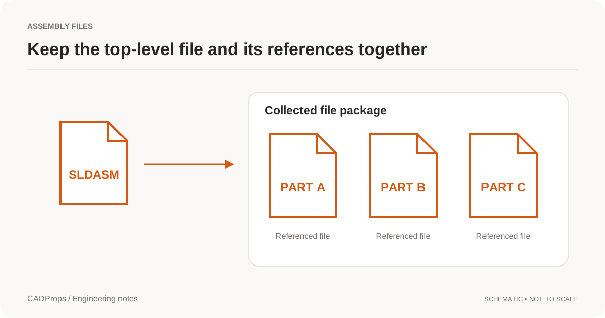
For assemblies, check that dependencies are resolved and that exclusions are intentional. A clean preview of loaded components does not prove that every required component was present.
Save the original input unchanged. If another export attempt is needed, return to the source rather than repeatedly converting the previous output.
2. Confirm the output requirement
Agree the target format and profile with the receiver. State whether component organization, names, colors or manufacturing information are required. Reader and writer capabilities are separate and may vary by format version. Translator format matrix.
Do not silently flatten an assembly or merge bodies to make an export succeed. Those are meaningful decisions about the deliverable. Get agreement and write the choice into the processing record.
3. Reopen the result
Where practical, inspect the file in the actual receiving system, not only the tool that created it. Confirm that the expected model loads and that no importer warning is being overlooked.
A format checker and a viewer answer different questions. NIST describes both analysis of STEP information and visual confirmation of the model. NIST validation overview. Neither a plausible thumbnail nor a file extension alone is a full acceptance check.
4. Verify units, placement and gross scope
Measure one known dimension. Inspect the coordinate frame and component placements. Confirm the bodies or components expected for the task.
Use volume or area comparisons as supporting checks only when both calculations have a valid and comparable scope. A property routine can return misleading results when geometry preconditions are not met. Open CASCADE property requirements.
Two models can share volume and bounding dimensions while differing locally. Do not call them identical on the strength of those totals.
5. Inspect the features that matter to the next task
Select a few functional regions: a mating face, a small bore, an internal pocket or a thin wall. The appropriate checks depend on what the recipient will do. A large outer silhouette is a poor test for a part whose important changes are inside it.
If the output was tessellated, check approximation around curves and narrow features. If a STEP file contains faceted geometry, document that representation rather than presenting it as recovered native surfaces.
Avoid undocumented automatic repairs. If a repair is necessary, retain the before-and-after artifacts and review the affected region.
6. Check non-geometric information separately
Names, quantities, appearances and PMI should each have their own status when required. Visual annotations and machine-readable manufacturing information are not the same thing.
An omitted optional color may be acceptable for one job. An omitted required annotation may not be. The acceptance decision comes from the agreed requirements, not from a generic “all data retained” message.
7. Make a compact check record
| Item | Result to record |
|---|---|
| Source revision and scope | Explicit file/version and selection |
| Output | Format, profile and producing tool |
| Reopen test | Application used and warnings |
| Units and known dimension | Checked value and unit |
| Components and placements | Checked / partial / not checked |
| Functional geometry | Regions inspected and limitations |
| Required metadata | Retained / not retained / not checked |
| Remaining issues | Plain-language exceptions |
Use “not checked” when that is the truth. A row of green ticks is less useful than a record that distinguishes evidence from assumption.
8. Deliver source, output and explanation together
Name files clearly, keep the revision consistent and include the record with the package. For a batch, provide one result per input and a source-to-output manifest. Do not discard failed rows to make the batch appear complete.
Share a fixed version or delivery package when review context matters. If a new result replaces an earlier one, identify the replacement explicitly. A recipient should not have to guess whether final-new-2.step supersedes the file they already reviewed.