

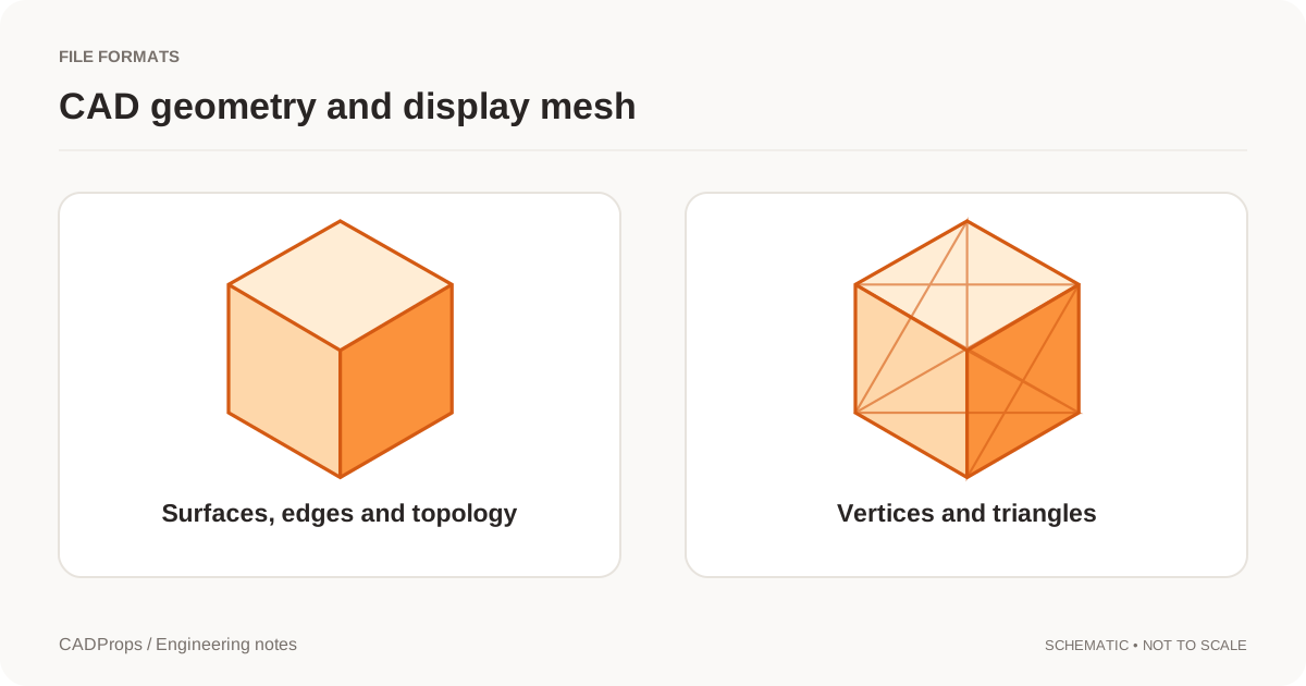
A STEP model can contain more information than a shaded preview shows. When a hole is represented by analytic cylindrical B-Rep geometry, software can inspect that geometry directly instead of estimating a diameter from screen pixels or a triangle mesh.
CADProps uses a deliberately conservative rule-based recognizer for a narrow set of holes in STEP geometry. In the current release it can classify full cylindrical through holes and flat-bottom blind holes in a single closed solid. The recognizer exposes the cylindrical radius and, when the feature passes the classification rules, the hole type and depth. Stepped, counterbored, partial, intersecting, conical-bottom and multi-solid cases remain unclassified rather than being guessed.
That boundary is important. “Hole recognition” is not the same as detecting every circular-looking shape in a model.
What STEP hole recognition actually examines
STEP commonly carries boundary-representation geometry: faces, edges, curves and their topology. A cylindrical hole can therefore be represented as an analytic cylindrical face bounded by circular edges. This is different from identifying a circle in a screenshot.
For a supported hole, CADProps checks the underlying B-Rep. The current recognizer requires a complete cylindrical wall, two complete circular rims and a single closed solid. It also checks which side of the wall belongs to the solid and traces the cylinder axis to distinguish an opening from a flat-bottom termination.
The same general idea appears in manufacturing-analysis software. CAD Exchanger's Manufacturing Toolkit documents feature recognition on B-Rep solids and lists multiple hole types among the features that can be returned by its recognizer. Its machining-feature documentation illustrates the broader industrial use of geometric feature recognition. CADProps currently supports a much narrower subset and does not claim parity with that toolkit.
Current CADProps hole-recognition scope
| Geometry | Current classification |
|---|---|
| Straight full cylindrical through hole | Supported when the single-solid checks pass |
| Straight full cylindrical blind hole with a flat bottom | Supported when the single-solid checks pass |
| Stepped hole | Unclassified |
| Counterbore / coaxial secondary cylinder | Unclassified |
| Countersink or conical-bottom hole | Unclassified |
| Partial cylindrical cut | Unclassified |
| Hole intersecting another feature | Unclassified |
| Multi-solid model | Hole classification is not applied |
“Unclassified” is intentional. It means the geometry does not satisfy the rules for the limited feature types above. It does not mean the model contains no hole, and it does not mean the file is damaged.
How to inspect a recognized hole
Start in the STEP viewer with the original file. Confirm the model is the expected revision, then check the overall dimensions and solid count before interpreting local features.
For a cylindrical face, CADProps can expose its analytic radius. The hole diameter is twice that radius. For a hole that passes the recognizer, the feature can also be labeled as through or blind and can expose the cylindrical depth used by the classification.
Use the CAD dimensions tool when you also need overall size or local measurements. Keep these concepts separate:
- diameter comes from the analytic cylindrical geometry;
- recognized depth describes the supported cylindrical feature extent;
- drawing depth may be defined by design intent, drill-tip allowance, a counterbore, a countersink or another convention not represented by this simple classification;
- tolerance is not inferred from nominal geometry alone.
A recognized Ø10 mm cylindrical hole therefore does not automatically mean “Ø10 H7,” nor does it establish a machining operation.
Why a circular face is not always a hole
A cylinder can also describe an outside shaft, boss or pin. The recognizer checks face orientation and the solid interior so an exterior cylinder is not simply renamed as a hole.
Trimmed geometry is another source of false positives. A slot ending in a semicircle, a side cut intersecting a bore, or a hole broken by another pocket can contain cylindrical surface fragments without being a complete simple cylindrical hole. CADProps rejects those cases from the current classification.
Coaxial cylinders are also significant. A counterbored hole may contain a large cylinder joined to a smaller cylinder on the same axis. The current recognizer deliberately rejects that configuration instead of labeling one cylinder as an independent simple hole and creating a misleading result.
Through holes versus blind holes
For a simple through hole, the cylindrical cavity opens out of the solid at both ends. For a supported blind hole, one end opens out of the solid and the other terminates at a planar face perpendicular to the cylinder axis.
The distinction sounds simple, but geometry can complicate it. A drill-point bottom is conical, not planar. A blind bore that intersects a side pocket may have an open path that changes the topology. A stepped feature can introduce multiple coaxial cylindrical regions. Those cases are outside the current conservative rule set.
This is preferable to silently assigning a confident label to ambiguous geometry. If a feature stays unclassified, inspect the faces directly and compare the part with the controlling drawing.
Hole recognition for quoting and process planning
Hole information can be useful before CAM programming. Diameter, type, depth and repetition are common inputs to manufacturing review, costing and process planning. The value is highest when the recognition result reduces manual counting while remaining traceable to the source geometry.
But a geometry recognizer does not know the complete manufacturing requirement. A nominal cylindrical cavity does not reveal all of the following by itself:
- dimensional tolerance;
- positional tolerance or datum scheme;
- surface finish;
- thread specification;
- whether the feature is drilled, bored, reamed or produced by another process;
- inspection requirements;
- whether a visually similar feature has a functional designation in the drawing.
Use recognized geometry as an analysis aid, not as a replacement for the drawing, PMI or manufacturing plan.
Why B-Rep recognition is different from mesh measurement
A triangle mesh approximates surfaces with facets. You can fit a circle or cylinder to mesh vertices, but the result then depends on tessellation quality and fitting tolerance. STEP B-Rep can preserve analytic cylinders and circles, so a compatible reader can query the mathematical radius directly.
That is why STEP is a better input for this particular feature analysis than a coarse STL export. Converting STEP to STL first can discard the analytic surface definition that made deterministic recognition possible.
If the only file you have is a mesh, use mesh-aware measurements and describe them as approximate. Do not present a fitted mesh diameter as if it came from the original analytic CAD face.
A practical verification workflow
When using hole recognition for an engineering check, use a repeatable sequence:
- Confirm the STEP file revision and units.
- Verify the expected solid loaded completely.
- Compare one known overall dimension with the drawing or sender's value.
- Select the cylindrical feature and inspect its radius or diameter.
- If a through/blind label appears, verify it visually against the surrounding geometry.
- Check the drawing for tolerances, threads, counterbores, countersinks or other design requirements that geometry recognition does not supply.
- Treat any unclassified feature as a manual-review case rather than forcing it into a supported type.
For broader measurement practice, read Measure STEP Files Online. For handoffs and conversions, use the CAD conversion checklist so recognized features are not separated from revision and geometry validation.
STEP hole recognition is most useful when it remains conservative: report the simple features that satisfy known geometric rules and leave the rest visibly unresolved.
Original article: CADProps · https://www.cadprops.com/guides/step-hole-recognition/