

A STEP file bounding box is a quick way to answer a practical question: how much space does this model occupy along X, Y and Z? It is useful for fit checks, rough stock planning, packaging discussions and sanity-checking a file before deeper inspection.
But a bounding box is not a drawing dimension, a minimum-volume box or a machining allowance. The result depends on the coordinate frame and on which bodies or assembly components are included.
If you only need the current overall size, open the file in the STEP dimensions tool. The checks below explain what those three numbers mean and when they can mislead you.
What a STEP bounding box measures
An axis-aligned bounding box finds the minimum and maximum coordinates of the selected geometry along the current X, Y and Z axes.
The reported size is therefore:
X size = Xmax - Xmin
Y size = Ymax - Ymin
Z size = Zmax - Zmin
For a rectangular block aligned with the axes, the result may match its familiar length, width and height.
For a rotated bracket, the same physical model can produce different X and Y extents because the axes did not rotate with the part.
That is not an error. It means the coordinate frame is part of the measurement.
Why a rotated part gets a larger bounding box
Imagine a long rectangular plate lying square with the X axis. Its X extent may be close to its actual length and its Y extent close to its width.
Rotate the plate around Z and both X and Y extents change. The part itself did not become larger. The axis-aligned box now has to cover the rotated silhouette.
This distinction matters when someone asks for the "smallest dimensions" of a model.
An axis-aligned box answers:
What are the extents in this coordinate system?
A minimum or oriented bounding box answers a different optimization problem:
What compact box can contain the part after choosing another orientation?
Do not silently substitute one for the other. For machining, shipping or nesting, the chosen orientation may have engineering consequences.
Bounding-box dimensions are not drawing dimensions
A CAD drawing dimension identifies a specific design requirement: for example, the distance between two machined faces or the diameter of a hole.
A bounding box does not know which features are functionally important. It only reports the outside coordinate extents of the included geometry.
That means a result such as:
X: 142.0 mm
Y: 86.5 mm
Z: 31.2 mm
does not tell you:
- the hole spacing,
- a flange thickness,
- the minimum clearance between two faces,
- the manufacturing tolerance,
- the stock allowance.
Use the STEP measurement guide when you need local geometry rather than only the overall envelope.
Verify the units before trusting the envelope
Bounding-box numbers are only useful when the scale is correct.
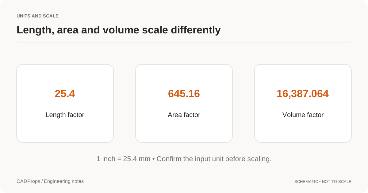
Check one dimension that you already know from the drawing, sender or source CAD system. If a part expected to be about 50 mm wide appears around 1,270 mm, the ratio is 25.4 and an inch/millimeter interpretation problem is a strong possibility.
Do not fix that by dragging a scale slider until the model looks reasonable.
The 25.4 scale-error guide explains how to distinguish unit interpretation from an intentional geometry scale change.
A viewer can fit a tiny or huge model to the same screen, so apparent screen size is not a unit check.
Decide what belongs inside the box
A STEP file can contain:
- one solid,
- several bodies,
- an assembly,
- repeated component instances,
- auxiliary or unintended geometry.
The overall box changes when the scope changes.
A stray body far from the intended part can make one axis unexpectedly large. A missing assembly component can make the box too small. Repeated instances can extend the assembly even though the unique part definition has not changed.
Before using an envelope dimension, inspect the component or body list and confirm that the intended geometry is loaded.
For supplier data, a useful note is:
Scope: complete housing assembly
Frame: source assembly coordinates
Bounding box: 420 × 265 × 190 mm
Units: mm
Missing components: none reported
That is much more reusable than a screenshot containing three unlabeled numbers.
Bounding box versus material volume
The box volume is simply:
X size × Y size × Z size
but that is not the part's solid volume unless the part completely fills the box.
A bracket with holes, pockets, chamfers and a curved profile can occupy a large envelope while containing far less material.
Do not use bounding-box volume for a weight calculation. Use geometry-based solid volume instead, then apply the intended material density.
The STEP volume guide explains that workflow.
Bounding box versus machining stock
A bounding box can be a starting reference for raw stock, but it is not automatically the correct stock size.
Real stock selection may need:
- saw allowance,
- facing allowance,
- clamping allowance,
- process orientation,
- standard bar or plate sizes,
- casting or forging stock,
- setup-specific clearances.
Those are manufacturing decisions outside a generic CAD envelope.
If the purpose is quoting, record the geometric bounding box separately from any stock allowance added by a process rule.
Why two viewers can show different dimensions
Different results do not always mean one tool is wrong.
Check whether the tools are measuring the same:
- unit interpretation,
- coordinate frame,
- body/component scope,
- transformed assembly placements,
- source geometry versus a derived mesh,
- included hidden or auxiliary bodies.
One viewer may report source-coordinate extents while another reports the model after a scene transform. One may measure the full assembly while another reports only the selected component.
Make the scope explicit before comparing the numbers.
Use the box as a fast sanity check
Bounding dimensions are especially useful early in a workflow.
Before converting, quoting or calculating weight, ask:
- Is the rough size plausible?
- Are the units plausible?
- Is an expected component missing?
- Is there a distant stray body?
- Does the orientation explain the envelope?
These checks catch many bad handoffs before more detailed work begins.
A practical STEP dimension workflow
- Open the STEP or STP file.
- Confirm the expected part or assembly is loaded.
- Read the X, Y and Z bounding dimensions.
- Verify one known dimension and unit.
- Record the coordinate frame and scope.
- Move to local measurements only when the task requires them.
The bounding box is most valuable when it is treated as a clearly defined geometric property, not as a substitute for every dimension in the design.
Original article: CADProps · https://www.cadprops.com/guides/step-file-bounding-box/