

STL does not provide a standard physical-unit declaration for its coordinates. A vertex coordinate of 25 does not, by itself, tell the receiver whether the intended length is 25 mm, 25 inches or another unit. The exporting and importing workflow has to agree on that interpretation. The Library of Congress format description notes this unit limitation in its STL format reference.
That is why the same STL can appear at the correct shape but the wrong physical size. The mesh is not necessarily damaged; the two applications may simply be interpreting the same coordinate numbers with different units.
The quickest test: measure one dimension you already know
Do not judge scale from the viewport. Most viewers automatically fit the model to the screen, so a 10 mm part and a 10 m part can look almost identical on screen.
Instead:
- Open the file in the STL viewer.
- Read the overall X, Y and Z extents.
- Pick one dimension you know from the source CAD model, drawing or specification.
- Compare the expected physical length with the STL coordinate extent.
- Only after the unit interpretation is confirmed should you scale, slice, quote or calculate approximate mesh properties.
If the source part is known to be 50 mm wide and the STL extent is about 50, interpreting the coordinates as millimeters is plausible. If a receiving application treats that same value as 50 inches, the physical model becomes 25.4 times larger.
Why 25.4 is the classic warning sign
One inch is exactly 25.4 mm. A model that is consistently 25.4× too large or 1/25.4× too small strongly suggests an inch/millimeter interpretation mismatch.
Examples:
| Intended size | Imported size | Likely clue |
|---|---|---|
| 2 in | 50.8 mm | Same physical size expressed in mm |
| 50 mm | 1,270 mm | 25.4× too large; investigate inch/mm handling |
| 50 mm | about 1.9685 mm | 1/25.4× too small; investigate inch/mm handling |
A 25.4 ratio is evidence, not permission to blindly rescale. Confirm the source unit and the import setting first. Assemblies, scene transforms and previous conversions can introduce other scale factors.
For a broader diagnostic workflow, read STEP and CAD scale wrong by 25.4.
STL units are a workflow convention, not embedded engineering metadata
Many 3D-printing workflows conventionally treat STL coordinates as millimeters. Other workflows can use inches or another agreed unit. The key point is that the STL itself does not reliably settle the question.
A filename such as bracket_mm.stl is helpful human context but it is not a standard machine-readable unit field. A slicer preference such as “assume inches” is also an import rule, not evidence stored inside the STL geometry.
For repeatable handoffs, record the intended unit beside the file and verify one dimension after import.
Changing display units is not the same as scaling geometry
These two actions are often confused:
- Unit conversion expresses the same physical size in another unit. A 25.4 mm length is 1 inch.
- Geometry scaling multiplies the coordinate values and changes the model's interpreted physical size under a fixed unit assumption.
If the coordinates are correct but the receiver assumed the wrong unit, fix the import/export unit interpretation when possible. Applying a geometric scale factor can hide the real workflow problem and cause the next application to scale the model again.
Keep the original STL unchanged. Save any corrected derivative with a clear note describing the factor, intended unit and reason.
What happens to area and volume when scale is wrong
A linear scale error propagates differently to area and volume.
If every length is multiplied by a factor s:
- surface area changes by
s²; - volume changes by
s³.
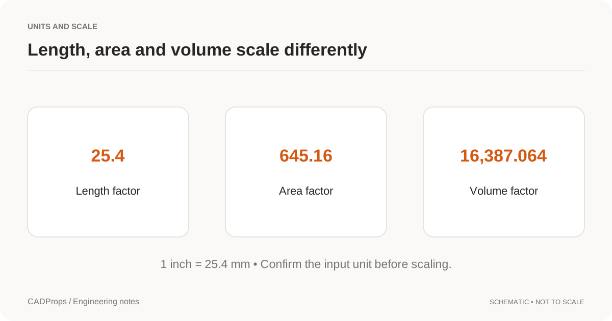
So an inch/mm mistake is not a small error in a weight estimate. A 25.4× length error corresponds to a 645.16× area factor and a 16,387.064× volume factor.
CADProps reports STL properties from the triangle mesh, so treat those values as mesh-derived approximations. Confirm the unit interpretation and mesh closure before using volume. Any mass calculation additionally depends on the density you choose and does not establish the source material specification.
How to prevent the problem when exporting STL
Before export, record the CAD model's unit and choose an STL export workflow whose receiving unit convention is understood. Then reopen the exported STL in a second application and measure a known dimension.
Also verify tessellation quality. Fixing units does not fix a coarse mesh, and increasing mesh resolution does not fix a unit mismatch. They are separate checks. The STL export settings guide covers mesh resolution, topology and repeatable export settings.
If the downstream process accepts a format that carries explicit units, consider whether STL is still the best handoff. STEP versus STL explains the difference between CAD solid exchange and tessellated mesh delivery.
A compact receiving checklist
When an STL arrives from somebody else, record:
- expected physical unit;
- expected revision or source model;
- one known dimension;
- measured X/Y/Z extents;
- any scale factor applied;
- whether the mesh is closed enough for the intended volume calculation;
- which application will consume the file next.
That turns “the STL looks the wrong size” into a reproducible diagnosis rather than a guess.
Measure an STL online before accepting its scale in a printing or manufacturing workflow.
Original article: CADProps · https://www.cadprops.com/guides/stl-files-have-units/