
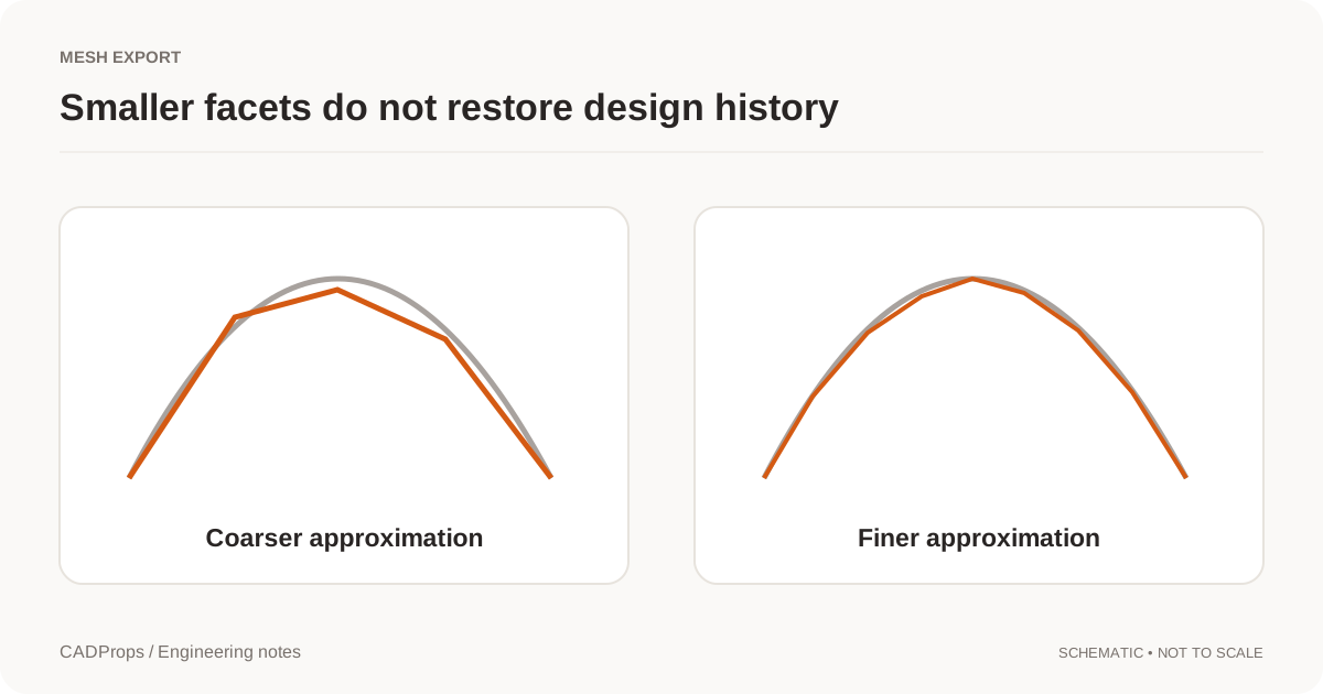
A low-resolution STL may show visible flats around a circular hole. A very dense STL may be slow to transfer or slice without providing a useful improvement. The right settings depend on the geometry and the job that will use the mesh.
Keep the engineering source and export a separate STL derivative. Record the unit convention and the settings used so that a later export can be reproduced rather than guessed.
What the exporter is approximating
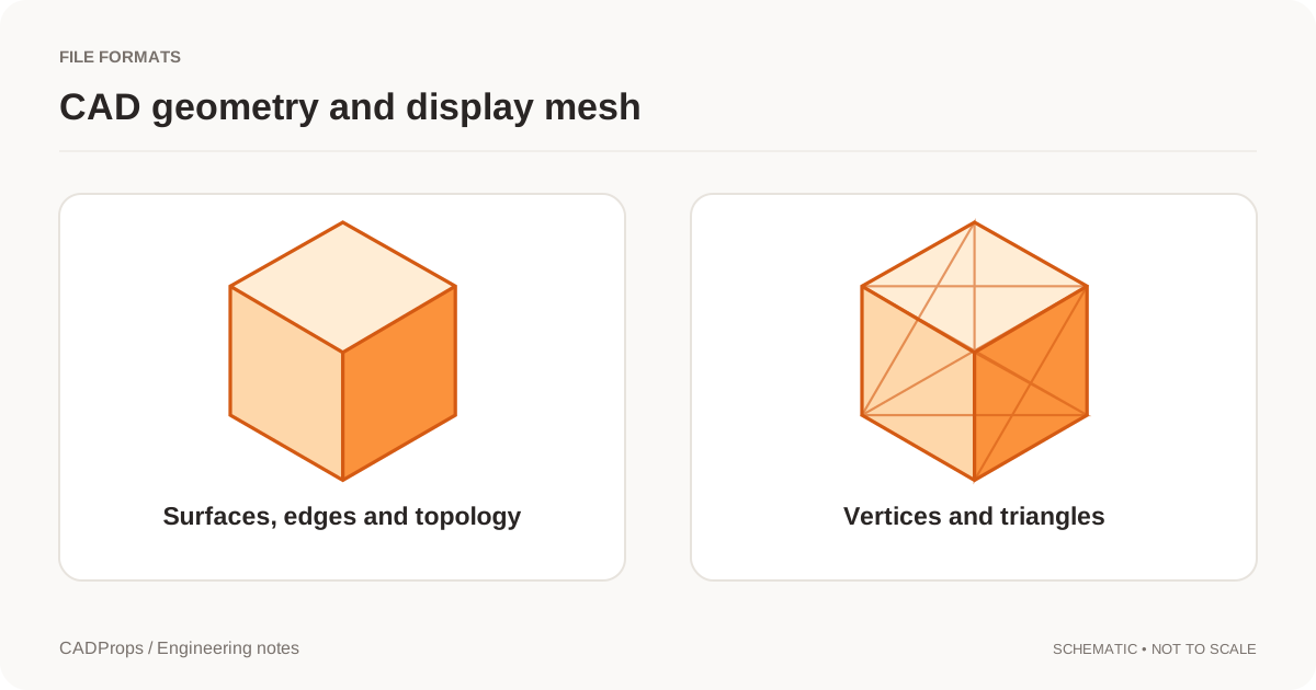
STL represents a surface with triangles. A curved CAD face therefore becomes a collection of flat facets. Increasing the resolution can approximate the shape more closely, but it does not preserve the original analytic surface or design history. STL format description.
A preview can hide facets through shading. Inspect the actual edge silhouette and relevant cross-sections instead of assuming a smooth-looking render means the mesh is sufficiently detailed.
Different exporters use different labels and definitions. Chord deviation, angular tolerance and maximum edge length are not interchangeable controls, and their exact behavior belongs to the exporter's documentation.
Start with the intended use
| Use | Main concern | What to inspect |
|---|---|---|
| Quick visual preview | Transfer and display cost | Overall silhouette and recognizable features |
| Print trial | Geometry usable by the printing workflow | Scale, closure and task-critical features |
| Detailed mesh analysis | Method-specific resolution needs | Local curvature and regions used by the analysis |
| CAD handoff | Whether STL is appropriate at all | Consider retaining STEP or native geometry |
Do not choose the coarsest mesh merely because it is small. Do not choose the finest available setting merely because it sounds accurate. Try one representative part and inspect the result in the actual receiving software.
Check small features explicitly
A large housing may contain a small bore or edge radius that matters to the job. The overall shape can look correct while that local feature is poorly approximated.
Compare the exported edge with the intended CAD boundary, especially where curvature changes quickly. Inspect thin walls and narrow gaps. A global triangle count tells you how large the mesh is, but not whether triangles are distributed where the task needs them.
If changing one setting solves a local problem, save a second export with a clear name and compare it. Avoid changing every setting at once when diagnosing a bad result.
Agree the units, then test one dimension
STL does not provide a standard physical-unit declaration. A coordinate value must be interpreted by the exporting and importing workflow. State the intended unit and verify it after import. Library of Congress format reference.
Unit problems can show up as a model that is consistently too large or small. A known linear dimension is the quickest check. Do not scale a file simply to make the preview fit the screen; a viewer's fit-to-window operation is not a unit conversion.
Keep “display units” and “change physical scale” as separate operations. They serve different purposes and should leave different records.
Check topology as well as appearance
A mesh can look fine while containing an open edge, overlapping surfaces or inconsistent orientation. Whether those defects matter depends on the downstream operation, but they should not be hidden.
For a closed-volume task, use appropriate validation before calculating a mass or passing the model to another process. If automatic repair changes the mesh, keep both versions and inspect the affected area. A repaired file is a new derivative, not necessarily a faithful reconstruction of missing design intent.
Binary, text and the wrong kind of simplification
STL has binary and ASCII variants. The choice affects storage and tooling compatibility, not an automatic improvement in geometric fidelity. The surface resolution remains a separate decision.
Mesh decimation after export also deserves a check. It can reduce size, but it may modify small regions. Keep an unreduced version and compare any task-critical feature before replacing the delivery.
Deliver a repeatable export
Record the source revision, unit convention, exporter and meaningful mesh settings. Keep the STL alongside its source reference, not as an unexplained file called final.stl.
CADProps processes self-contained STEP/IGES geometry, supported static meshes and bounded ZIP packages. STEP pairs support solid differences; other 3D inputs support visual comparison. DWG provides 2D previews when the reader is installed. Native CAD formats and downloadable model conversion are not available. Open the STEP workspace.