

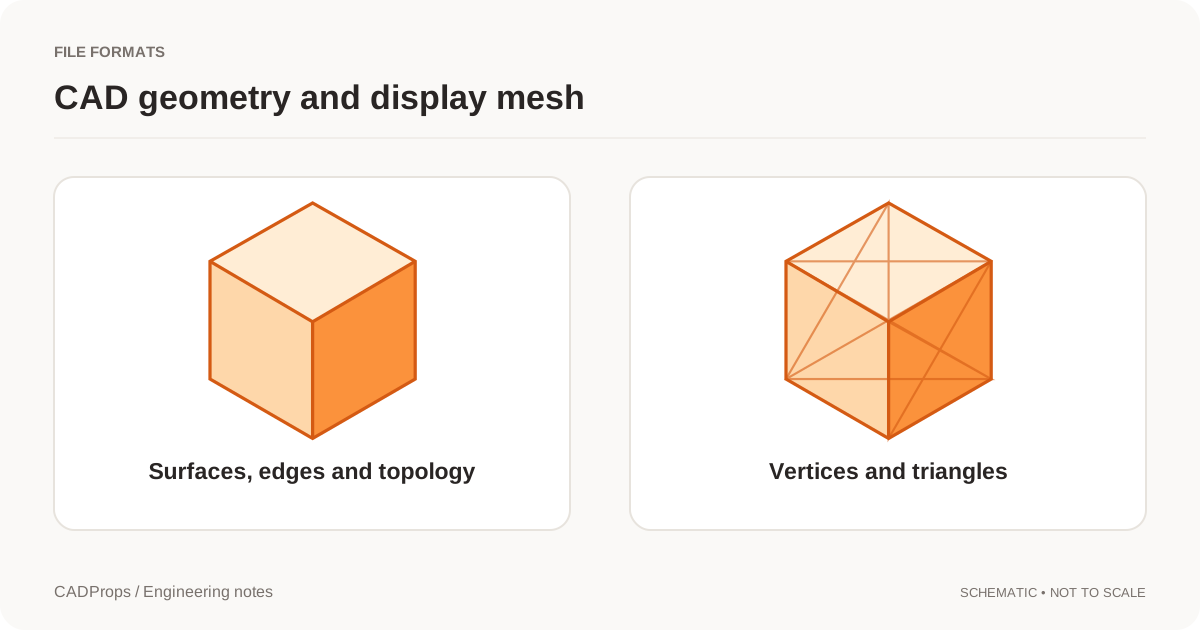
Tessellation replaces curved CAD faces with triangles. Viewers do it to draw a model. STL, OBJ and glTF exports do it because those formats store a mesh. The triangles are an approximation. They are not a more precise form of the solid, and they are not a record of the original faces.
A coarse mesh makes a round hole look polygonal. A fine mesh can look smooth and still be a mesh. Increasing the number of triangles does not recover the analytic cylinder, the feature tree or a unit declaration the mesh format never had.
Where you meet tessellation on this site
The shaded view of a STEP or IGES model is a display mesh. Properties for those formats are calculated from B-Rep when that geometry is available, not from how finely the picture was triangulated. What B-Rep means separates the two.
A STEP to STL file is a tessellated delivery. STL and OBJ coordinates are assumed to be millimetres because those formats do not reliably declare a unit. 3MF can carry a declared unit that is converted to millimetres. glTF is in metres and is normalized to millimetres for measurement. In every mesh case, dimensions and area are approximate, and volume exists only for a closed, consistent mesh.
What changes when the mesh gets finer
Chord height, angle and other export tolerances decide how far the triangles may stray from the source face. Those settings are the control. Adding decimal places to the filename is not.
Finer tessellation usually means:
- a closer visual match on curves;
- a larger file;
- a mesh measurement that can change slightly, because the approximation changed.
It does not mean the mesh volume has become the B-Rep volume. For the published synthetic block, the STEP solid is 40 × 30 × 20 mm, with volume 24,000 mm³ and area 5,200 mm². Those figures are the analytic solid in the sample library. They are not a measured error table for customer uploads, and they are not a promise that an STL of a different part will match its source to a stated percentage. This site does not publish aggregate statistics from real customer files.
If you need the solid's volume, measure the STEP or other B-Rep. If you need a print mesh, export STL at a tolerance the process accepts and check one known dimension after import. STL export settings covers resolution separately from units.
Checks after tessellation
- Record the source revision and the export tolerance if you know it.
- Open the mesh in the STL viewer or the matching mesh tool.
- Compare one known length with the CAD model. A 25.4 factor is an inch/millimetre problem, not a triangle-count problem.
- Confirm the mesh is closed before using volume. Watertight meshes explains why a visible part can still have no volume.
- Keep the original STEP or native file. A later request for precise geometry cannot be answered from the triangles alone.
Mass from a mesh is the approximate volume times a density you choose. Both inputs have to be stated, or the mass is not interpretable.
Diagnose faceting without changing the wrong setting
Suppose a round mounting hole looks like a polygon after export. First reopen the CAD source and inspect the same region. If the source remains cylindrical and the mesh contains large flat facets, resolution is the likely question. If both files have the wrong physical diameter by the same factor, investigate source scale before changing tessellation.
Make two mesh exports from the same revision using documented settings in the authoring application. Compare the hole silhouette, the smallest relevant feature, file size and import behavior. Keep the receiving application's resolution requirement with the chosen output. CADProps can inspect the resulting meshes; this workflow does not imply it exposes every tessellation control available in a desktop exporter.
| Symptom | First check | What increasing resolution cannot repair |
|---|---|---|
| Polygonal curve | Source curvature and export tolerance | Wrong source dimensions |
| Small opening disappears | Feature size and local triangles | A feature omitted from the source |
| Volume unavailable | Closure and orientation | Broken or missing boundary faces |
| Very slow preview | Triangle count and required detail | Missing external resources |
A mesh chosen for a web preview may reasonably contain less detail than one prepared for an agreed print process. Identify the intended use in the delivery note instead of calling either output universally “high quality.”
Original article: CADProps · https://www.cadprops.com/guides/cad-tessellation/