
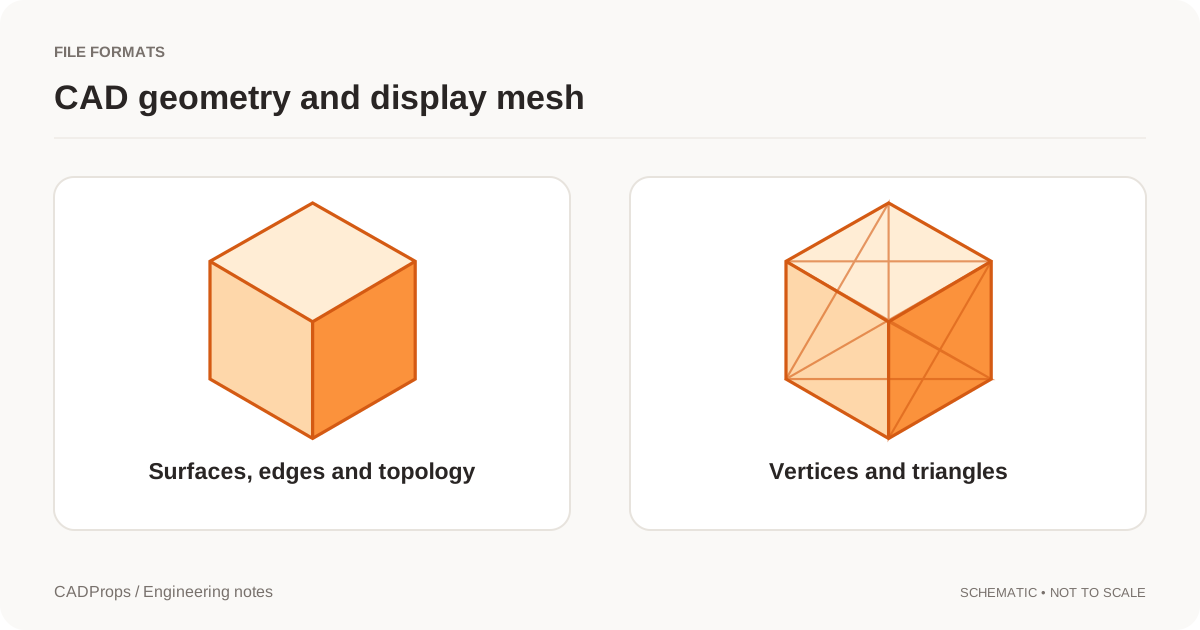
A supplier asks for STEP. A print service asks for STL. Both files can display the same bracket, but they are not interchangeable descriptions of the design. Choose the deliverable by what the recipient needs to do next, not by which thumbnail looks better.
STEP is used for exchanging product model data between engineering applications. STL describes a triangulated surface. That difference affects how curves are represented, what can be measured and what information is available after import. NIST's STEP overview and the Library of Congress STL description are useful starting references.
Geometry exchange versus a triangle surface
An engineering STEP file can carry boundary-representation geometry and associated product information. A cylinder may be represented by an analytic surface rather than by a ring of flat triangles. The actual content depends on the selected STEP schema, the exporter and the receiving system.
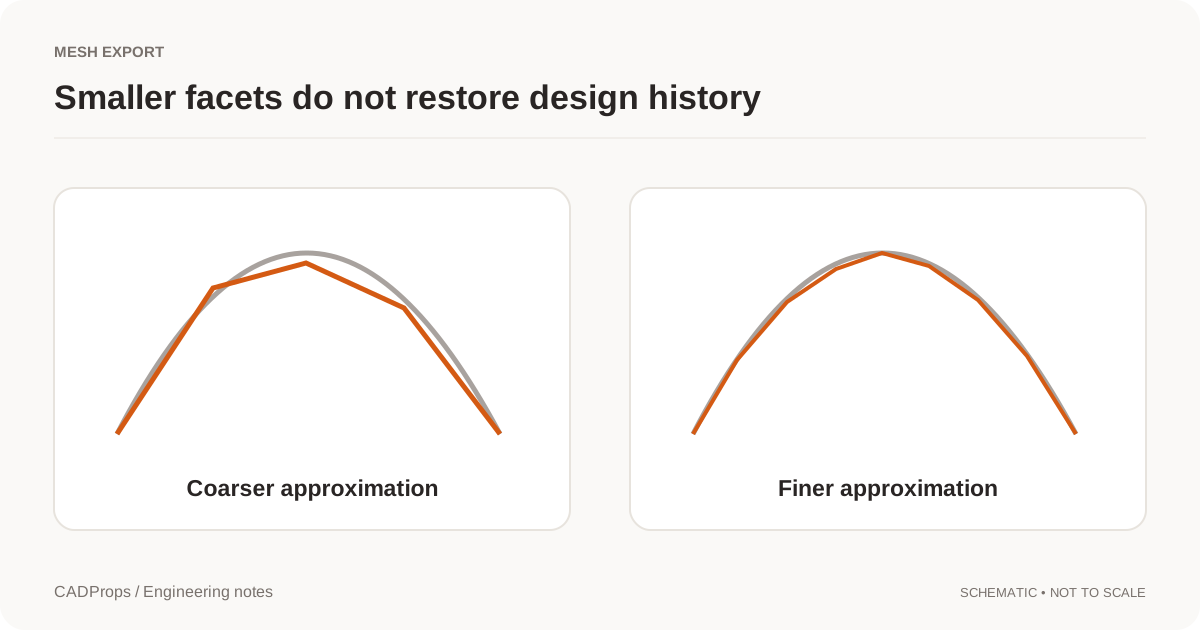
An STL file approximates the boundary with triangles. A coarse mesh makes a round edge visibly polygonal. A finer one can look smooth, but it remains a mesh; the original construction choices have not been recovered.
Avoid the shorthand “STEP is always exact.” STEP is a family of representations, and an exporter can place faceted geometry in a STEP container. Read the file's content and the translator's capability statement rather than trusting the extension.
A task-based choice
| Next task | A useful starting point | Important caveat |
|---|---|---|
| Cross-CAD geometry handoff | STEP | Test the receiving reader and required data |
| Mesh-based printing workflow | STL or the printer's agreed format | Check scale and mesh quality |
| Original parametric editing | Native design files | Include compatible versions and dependencies |
| Browser presentation | A display format or generated preview | Keep engineering source files separately |
A recipient's stated requirement overrides a general preference. Ask what their process accepts, including units, body structure and any required annotations. Sending every possible format is not the same as agreeing the correct one.
What is lost when you tessellate
Moving from curved geometry to triangles is a sampling decision. Small radii, narrow slots and thin edges need enough resolution for the receiving purpose. Export settings determine the approximation; increasing the number of decimal places in the filename does not improve it.
STL also lacks a standard place to carry a physical unit declaration. A coordinate value of 25 has to be interpreted by the workflow. Agree millimeters or inches and verify a known dimension after import. The usual grayscale STL preview should not be taken as proof of a material, color specification or manufacturing finish.
If you need a STEP handoff later, keep the original CAD or original engineering STEP. Going from a mesh back to a STEP file may package planar faces, but it does not automatically reconstruct the curves, design history or intent that existed before tessellation.
Can you calculate volume from either file?
Potentially, but the prerequisites differ and the reported method matters. A closed, correctly oriented surface can support volume calculations. Gaps, overlapping shells or inconsistent orientation can make a result invalid or misleading.
For CAD solids, the geometry kernel also has validity requirements. Open CASCADE's property documentation explicitly warns that some preconditions are not checked automatically by the volume routine. BRepGProp reference.
For a mesh result, describe it as a mesh-based estimate and record the mesh settings. For either representation, make sure the calculation covers the intended bodies. A believable number is not a substitute for checking the input.
What to send with the model
Include the revision, units and intended use. For an engineering handoff, also include the controlling drawing or agreed specification when required. A model file does not by itself tell the recipient which revision has been approved for manufacture.
A useful message is: “STEP for the CAD handoff, STL for the print trial, both exported from revision B in millimeters.” If the exports were made from different revisions, resolve that before sending them.
Check the conversion where it matters
After STEP-to-STL conversion, inspect a curved edge, a small hole and any thin region that matters to the task. Recheck a known size in the receiving application. For a STEP transfer, also check body or component scope and the information the next system relies on.
There is no single best extension for every handoff. There is a file representation that fits the next task, plus a short set of checks that makes the transfer defensible.