

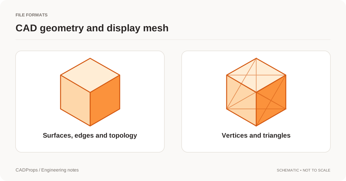
3MF and STEP can both move a 3D design between systems, but they preserve fundamentally different kinds of information. STEP is primarily a product-model exchange standard for engineering CAD data. 3MF is a structured manufacturing package built around mesh geometry and additive-manufacturing workflows.
The right choice depends on what the next system must do with the file. If the receiver needs exact CAD faces, assemblies, dimensions/PMI where supported, or a solid-model handoff for CAD/CAM, STEP is normally the stronger starting point. If the receiver needs a print-oriented package with declared units, multiple objects, colors/material information and additive extensions, 3MF may be the better fit.
The 3MF Consortium describes the format as more than a mesh: its core specification defines geometry, units, transforms and metadata, while published extensions add materials and manufacturing information. The current specification suite is recognized as ISO/IEC 25422:2025. See the 3MF specification.
NIST describes STEP (ISO 10303) as a product-model data standard used across CAD, CAM, CAE and inspection, with support for parts, assemblies and Product and Manufacturing Information. See the NIST STEP File Analyzer and Viewer.
3MF and STEP at a glance
| Question | 3MF | STEP |
|---|---|---|
| Core geometry | Triangle mesh | CAD product geometry, commonly B-Rep solids/surfaces |
| Declared units | Yes | Yes in normal CAD exchange workflows |
| Multiple objects/instances | Yes | Yes, depending on product structure/export |
| Exact analytic CAD faces | Not the core representation | Commonly preserved |
| Additive-manufacturing metadata | Strong format focus | Not the primary purpose |
| PMI / tolerances | Not the primary CAD-MBD route | AP242 can carry PMI when exporter/importer support it |
| Typical downstream use | 3D printing / AM package | CAD/CAM/CAE/CMM exchange |
| CADProps geometry properties | Mesh approximations | Solid-based properties when valid solids are available |
This table is about format capability, not a guarantee that every application writes or reads every optional field.
Choose STEP when the next step is CAD or CNC
STEP is usually the safer engineering handoff when the receiver needs to:
- import the model into another mechanical CAD system;
- create CNC toolpaths from exact solid/surface geometry;
- inspect B-Rep faces and edges;
- preserve an assembly structure where supported;
- carry model-based product information through an AP242 workflow;
- validate solid volume or surface area from CAD geometry.
NIST notes that STEP is used for interoperability between CAD, manufacturing, analysis and inspection software. That broader engineering role is why a STEP file remains a common supplier and machine-shop handoff even when a lightweight mesh would be easier to render.
Use the STEP viewer to inspect loaded bodies, units and geometry status before relying on a supplier model.
Choose 3MF when the deliverable is an additive package
3MF was designed to improve on common weaknesses of simple STL handoffs. The 3MF Consortium highlights defined units, closed geometry requirements, multiple objects and extensions for materials/properties.
That makes 3MF attractive when the receiver needs a print-oriented package rather than editable CAD design intent.
Examples include:
- arranging multiple print objects;
- preserving declared units rather than assuming them;
- carrying color/material-related information supported by the relevant 3MF extensions;
- packaging resources together instead of managing a loose set of files.
CADProps currently treats 3MF as a mesh inspection workflow. The 3MF viewer can inspect core triangle geometry, declared units and repeated component instances. It does not interpret the full set of additive-manufacturing extensions, and geometric properties are mesh approximations.
A 3MF mesh is not a STEP solid with a different extension
Converting between the formats changes representation.
A CAD cylinder in STEP can be represented as an analytic cylindrical face bounded by topology. In 3MF, the same apparent cylinder is represented by triangles. With enough triangles it can look smooth, but the receiving system is still working from tessellated geometry.
That matters for:
- precise edge/face selection;
- downstream feature recognition;
- surface-area/volume calculation method;
- re-editing geometry;
- CNC toolpath generation on exact surfaces.
Do not rename .3mf to .step. A real conversion must reconstruct or export an appropriate CAD representation, and not every mesh can be converted back into a clean parametric or exact solid model.
Units are better defined in 3MF than STL, but that does not make it a CAD replacement
One reason 3MF is attractive for additive workflows is that units are part of the format. That avoids the classic STL problem where coordinates can be interpreted as millimetres or inches by convention rather than by a reliable standard field.
But unit handling is only one dimension of fidelity. A STEP model may preserve exact solid topology that a print mesh does not. Choosing a format based only on whether it stores units misses the larger engineering question.
For the mesh-specific comparison, read 3MF vs STL.
Keep the manufacturing master separate from the print derivative
A good workflow often keeps both formats rather than forcing one to replace the other:
- keep the native CAD model as the design master;
- export STEP for neutral engineering exchange;
- generate 3MF for the additive-manufacturing job;
- record which revision produced each derivative;
- verify the derivative before release.
That separation prevents a print-oriented mesh from quietly becoming the only engineering record.
A practical decision table
Choose STEP if the next question is:
- “Can the machine shop import this into CAM?”
- “Can we measure exact CAD geometry?”
- “Can another mechanical CAD system read the solids?”
- “Can we preserve product structure or PMI where supported?”
Choose 3MF if the next question is:
- “Can the print job preserve units and multiple objects?”
- “Can we package richer additive-manufacturing information?”
- “Can we avoid STL's unit ambiguity?”
And keep the source CAD in either case. Neither neutral exchange nor a print package recreates the original feature history by magic.
If you convert or export between formats, use the CAD conversion checklist to verify scale, scope and geometry after the handoff.
Original article: CADProps · https://www.cadprops.com/guides/3mf-vs-step/