

CAD Guides: STEP Measurement, Weight & File Formats
Practical notes on CAD formats, model properties, units and engineering handoffs.
Engineering guides
26 guides
No matches. Clear the search or choose another category.
 Batch & handoff
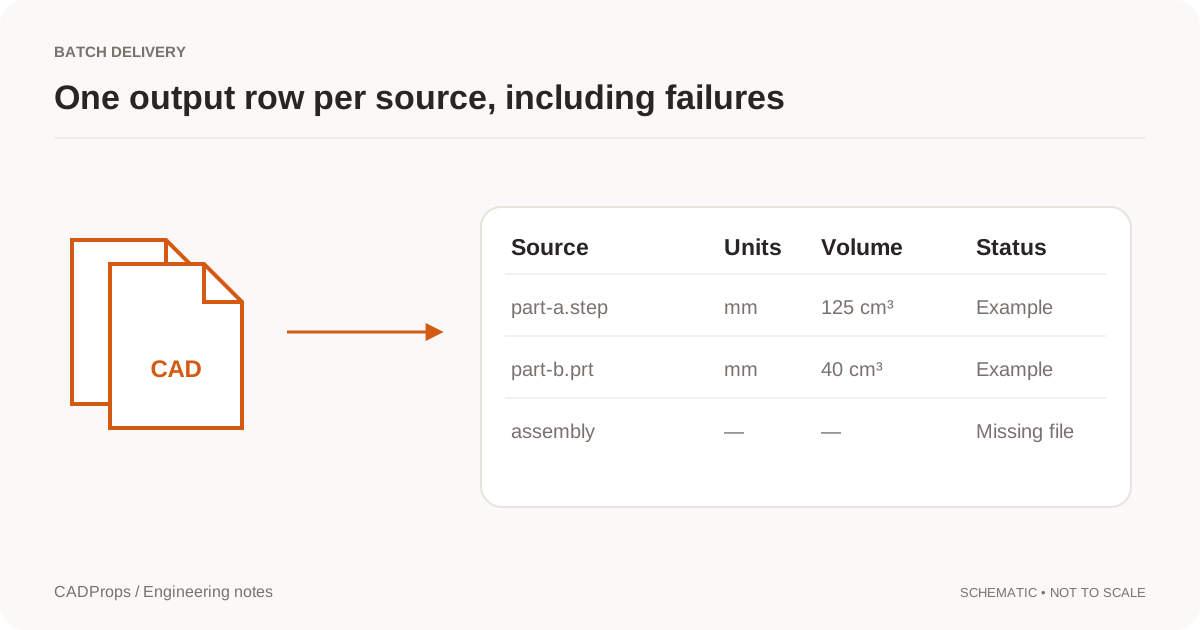
Export STEP Properties to Excel: Batch CAD Measurements
Design a useful batch report with one row per defined item, explicit units, material inputs and an exceptions list.
Take a closer look →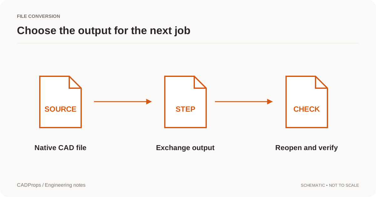 Conversion
CAD File Conversion Checklist: Units, Solids & Accuracy
Reopen the output, verify scope and units, inspect critical geometry, and include a short record of what was and was not checked.
Take a closer look →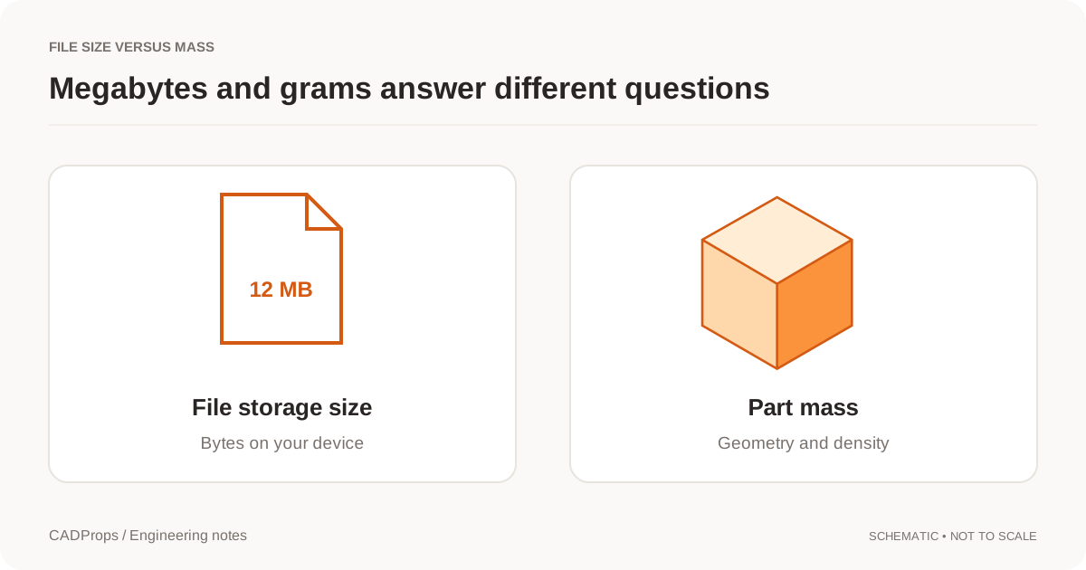 Measurement
CAD File Size vs Part Weight: Why MB Does Not Mean Mass
Megabytes describe storage. Grams describe mass. Here is why a large file can represent a light part, and what you need for a useful mass estimate.
Take a closer look →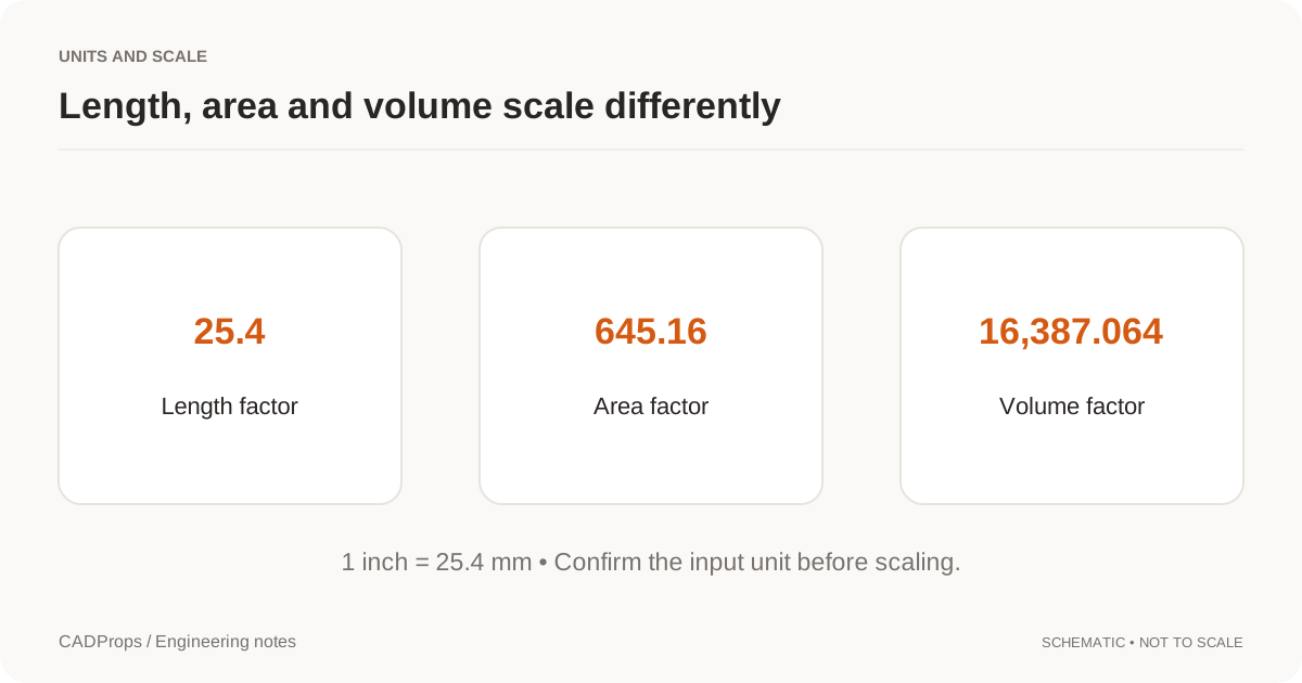 Measurements
CAD Model Scale Wrong by 25.4? Fix Inch and mm Units
Diagnose inch-to-millimeter scale errors without resizing by eye. Compare a known length, check import settings and keep area and volume units separate.
Take a closer look →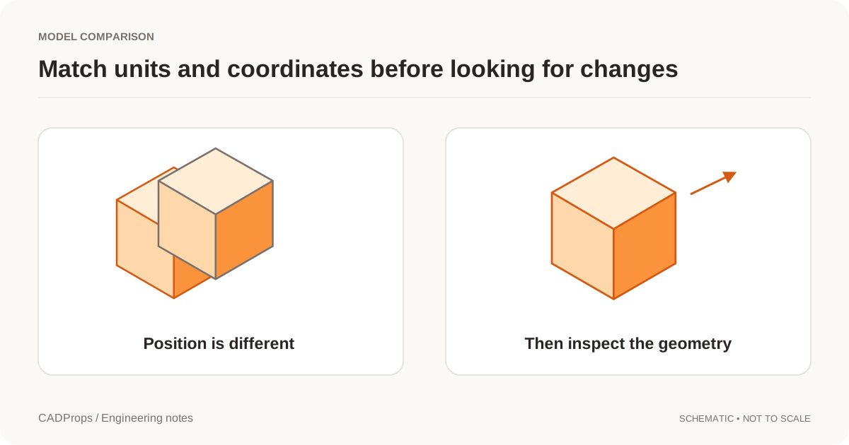 Versions & review
CAD Versions vs Revisions: Track Models and Exports
Keep upload history, engineering revision labels and converted files separate so a new export does not masquerade as a design change.
Take a closer look →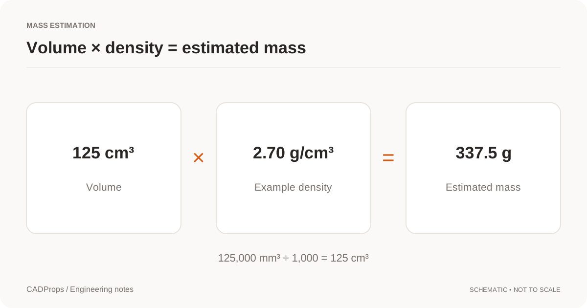 Measurement
Calculate STEP File Weight from Volume and Density
Work from valid solid volume, choose a documented density and keep units, configuration and assembly scope visible in the result.
Take a closer look →Versions & reviewCompare CAD Revisions: Geometry and Property Checks
Use fixed versions, explicit units and a deliberate alignment method before interpreting overlays or property differences.
Take a closer look → File formats
GLB vs glTF for CAD: 3D Model Files, Assets and Units
Use a display derivative for the web while keeping engineering geometry and revision records separate.
Take a closer look →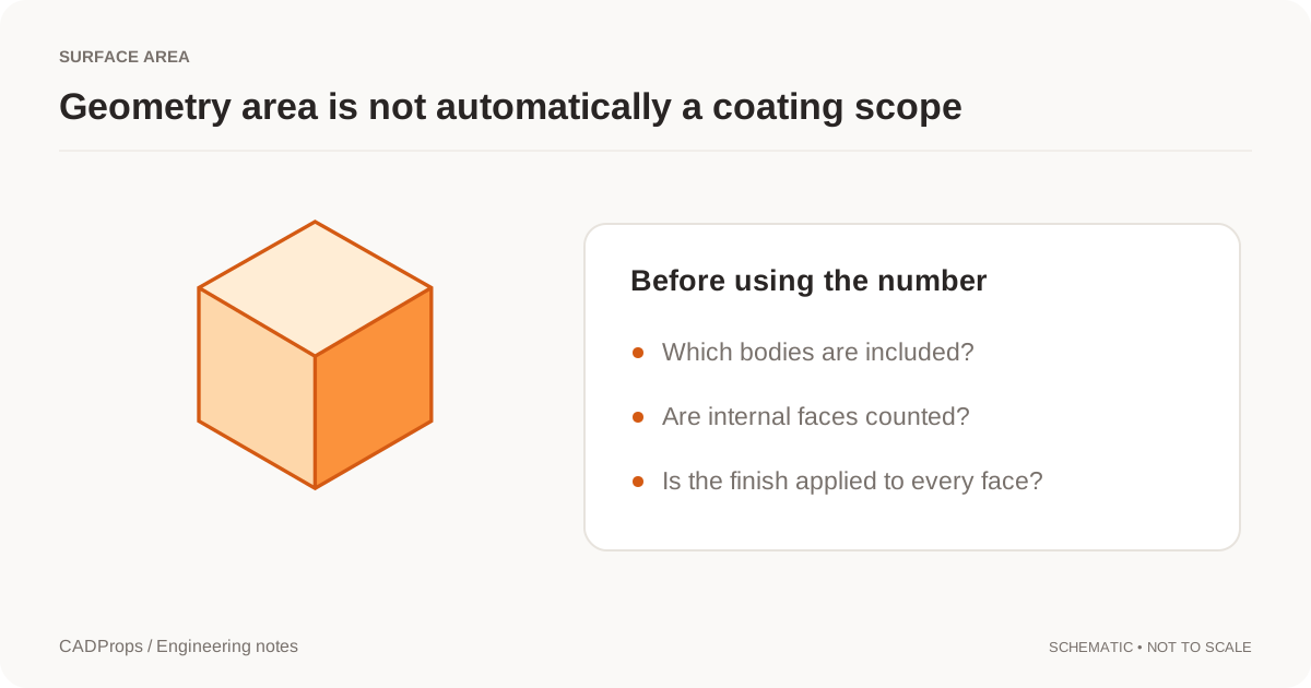 Troubleshooting
IGES Surfaces Not Solid? Check Volume and Open Shells
Understand an IGES surface import before stitching boundaries or assuming the reader failed to create a solid.
Take a closer look →MeasurementMeasure STEP Files Online: Dimensions, Distances & Units
Read a CAD model without confusing bounding-box dimensions, selected geometry measurements and drawing tolerances.
Take a closer look →ConversionExport NX PRT to STEP: Units and Assembly Checks
A practical NX-to-STEP handoff checklist covering PRT identification, configuration, units and post-conversion checks.
Take a closer look →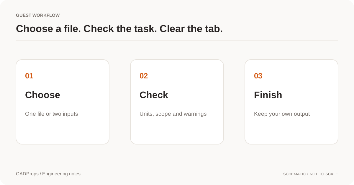 Opening files
Open CAD Files on Mac: STEP Viewers and Format Options
A practical Mac workflow for STEP, SLDPRT and NX PRT files: identify the format, check browser or desktop options, and verify the result.
Take a closer look →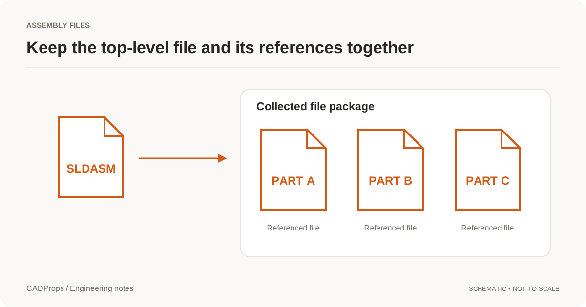 Opening files
Open SLDPRT Files Without SolidWorks: Viewer Options
Choose between a native viewer and a neutral export, check the file version, and know what a preview can and cannot tell you.
Take a closer look →File formatsParasolid vs STEP: CAD Geometry and Exchange Formats
Choose an exchange route by the receiving application and required data, not by assuming one file extension always converts better.
Take a closer look →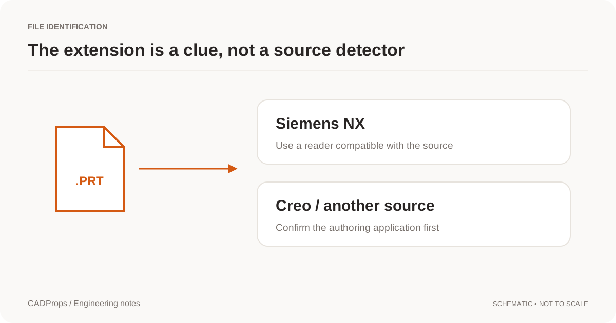 Opening files
NX or Creo PRT File? Identify the CAD Format
PRT does not uniquely identify Siemens NX. Check the sender, application version, dependencies and reader before attempting a conversion.
Take a closer look →Batch & handoffShare CAD Files with Suppliers: STEP Handoff Checklist
Prepare a small delivery package that identifies the model revision, intended use, units and any excluded components.
Take a closer look →Versions & reviewShare a Fixed CAD Revision: File and Version Checklist
Pin a shared model or comparison to an explicit version, check recipient permissions and handle replacements without silent updates.
Take a closer look →Opening filesSolidWorks SLDASM Missing Parts: Assembly File Checks
Troubleshoot an incomplete SolidWorks assembly by checking references, configurations and the contents of the delivery package.
Take a closer look →TroubleshootingReduce STEP File Size: Keep Required CAD Geometry
Distinguish archive compression, model simplification and display optimization before changing a CAD handoff.
Take a closer look →File formatsSTEP AP203 vs AP214 vs AP242: Colors and CAD Data
Understand STEP application protocols without treating the highest version number as a guarantee that every CAD reader preserves the same data.
Take a closer look →File formatsWhy STEP Files Lose the SolidWorks Feature Tree
A neutral CAD export can preserve useful geometry without preserving the original feature history. Learn what to request and what not to promise.
Take a closer look →File formatsSTEP vs STL: CAD Measurement, Geometry and Accuracy
STEP and STL serve different jobs. Learn what changes when surfaces become triangles and which checks belong in a CAD handoff.
Take a closer look →File formatsSTEP vs STP Files: Extensions and CAD Compatibility
STEP and STP are common extensions for the same exchange format. Learn what renaming changes, what it does not, and which checks matter more.
Take a closer look →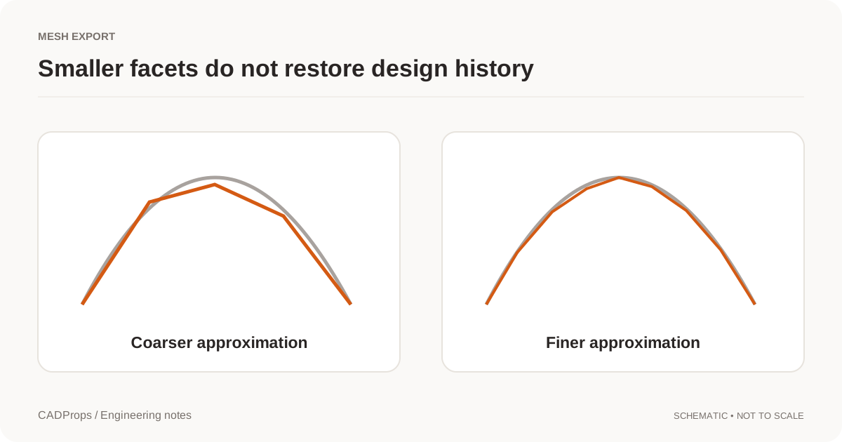 Conversion
STL Export Settings: Mesh Resolution, Units and Scale
Choose tessellation settings for the receiving task and verify curved features, thin regions and units after exporting.
Take a closer look →MeasurementsCalculate CAD Surface Area: STEP Faces and Assemblies
Define the faces, bodies, units and purpose before using a CAD surface-area total for coating, finishing or an engineering report.
Take a closer look →TroubleshootingSTEP File Volume Zero or Missing? Check Solid Geometry
Check whether the file contains valid solids before changing density or export settings. Missing volume is not the same as an empty part.
Take a closer look →