
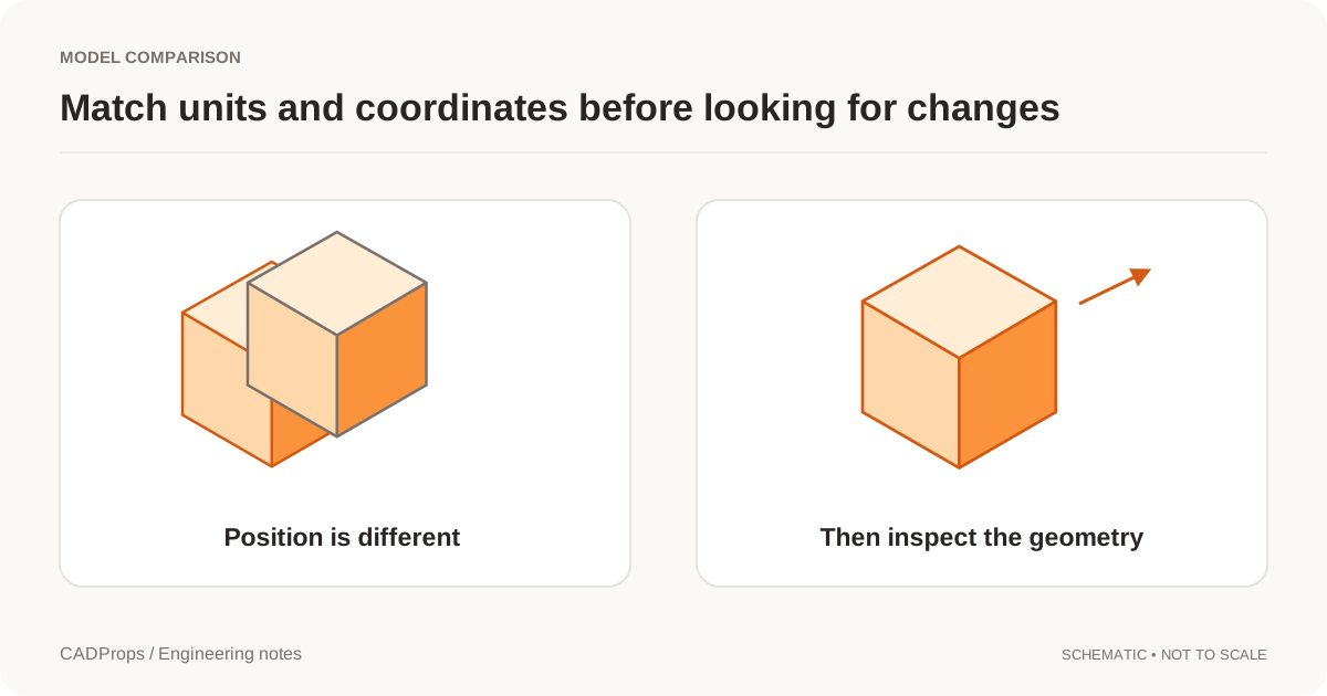
A red-and-blue overlay can look like a major design change when one file was simply exported in a different coordinate system. Before reviewing the colored regions, establish that the two models are the intended revisions and that the comparison conditions make sense.
A useful comparison starts with a question: are you checking placement, shape or both? Automatic alignment can help inspect shape, but it can also hide a placement change that was important to the assembly.
Fix the two inputs first
Record the exact earlier and later files. If the system supports saved versions, compare fixed snapshots rather than two links that always resolve to “latest.” Onshape's version documentation provides an example of immutable design snapshots, distinct from an active workspace. Versions and history.
Keep conversion outputs attached to their source revision. A STEP exported from V2 is not V3 simply because a new file appeared. If you compare a native file with a derivative, include that relationship in the record.
For assemblies, ensure that each revision includes its own dependencies. Loading an old top-level file with newer component files is not a reliable reconstruction of the earlier assembly.
Start with the original coordinates
Inspect units, orientation and placement before making an alignment choice. If both models use the same frame, a direct overlay preserves meaningful positional differences.
When the purpose is shape comparison, a deliberate rigid alignment may help. Record the transform and let the reviewer confirm it. Do not allow automatic scaling or mirroring to make different designs appear alike.
Two models can have the same envelope and volume yet differ locally. Those properties are useful warning signals, not proofs of geometric identity.
Use visual modes for what they actually show
| Mode | Good use | Limitation |
|---|---|---|
| Side by side | Overall form and component context | Small changes can be hard to locate |
| Overlay | Position and outline comparison | Overlapping colors are not a computed difference |
| A/B toggle | Checking one region in a fixed view | Relies on human inspection |
| Property table | Extents, volume and other summary differences | Equal totals do not prove equal shapes |
Label overlay colors as Model A and Model B unless a difference algorithm has actually classified added and removed material. The legend should describe the result that exists, not the result you hope to add later.
Separate a display threshold from engineering acceptance
A geometric comparison may use a distance threshold. Record its value, unit and calculation method. That parameter is a detection setting, not a tolerance specification for manufacturing.
“No difference detected within this threshold and scope” is more precise than “identical.” The former leaves room for sampling limits, untested components and algorithm constraints. A coarse preview should never be the hidden basis of a confident dimensional claim.
When a reviewer needs to know whether a hole moved, identify and measure that region with an appropriate method. Do not invent a feature-level explanation from a color patch alone.
Keep human notes separate from computed observations
A note saying “increase the bore to 8 mm” is a request. A user comment saying “the bore has changed” is an observation. A measured diameter difference is another kind of result. Give each an explicit label.
Attach comments to a version pair and view. Store the camera and section state so that the next person can inspect the same area. Avoid automatically attaching an old face marker to a new face unless the relationship has been verified.
Share the comparison, not just two filenames
A review package should include the version pair, configuration or body scope, unit choice, alignment method and saved observations. Fix that package when sharing it. A later upload should not silently replace one side.
CADProps processes self-contained STEP/IGES geometry, supported static meshes and bounded ZIP packages. STEP pairs support solid differences; other 3D inputs support visual comparison. DWG provides 2D previews when the reader is installed. Native CAD formats and downloadable model conversion are not available. Open the STEP workspace.