

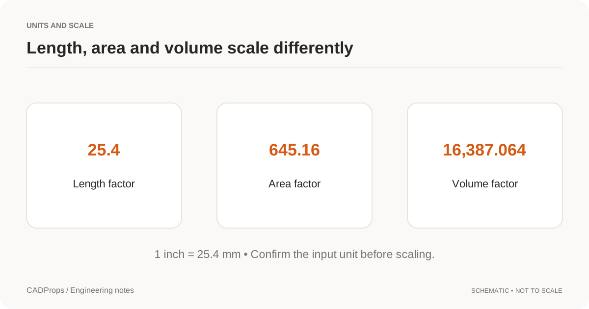
A DXF that looks 25.4 times too large or too small is usually a unit interpretation problem, not a reason to resize the geometry by eye.
This matters most when the drawing is headed to a laser cutter, router, waterjet or another 2D manufacturing workflow. A profile that is geometrically correct but interpreted in inches instead of millimetres can become an expensive scrap part.
The safest first check is simple: keep the original file unchanged, identify one dimension you trust, and compare the expected physical size with the imported result.
Start with one dimension you already know
Do not use fit-to-screen as evidence. A viewer can make a 20 mm bracket and a 2 metre panel occupy the same screen area.
Instead, write down four values:
| Check | Example |
|---|---|
| Expected size | 100 mm |
| Imported size | 2,540 mm |
| Ratio | 25.4 |
| Likely question | Was inch/mm interpretation applied incorrectly? |
A 25.4 ratio points toward inch-versus-millimetre interpretation because one inch is exactly 25.4 mm. It is a diagnostic clue, not automatic permission to scale the drawing.
Use the DWG/DXF viewer to inspect the drawing and compare a known length. If the drawing contains dimensions or annotations, treat them as references only until you know they belong to the same geometry and revision.
Drawing units and physical scale are related but not identical
CAD applications can store or infer drawing-unit information in different ways. Autodesk documents the AutoCAD INSUNITS setting for insertion scaling; it can also be set to Unspecified. Autodesk's DWG/DXF import workflow exposes both detected units and an explicit unit override. See AutoCAD INSUNITS and the DWG/DXF import unit workflow.
That means a receiving application may respect stored drawing units, use a template default, ask the user to specify units, or treat the geometry as unitless and apply no conversion. The coordinates alone do not always tell the next application whether the designer intended millimetres, inches or another unit.
Diagnose before changing the coordinates
Use this sequence:
- Keep the received DXF unchanged.
- Confirm the intended unit with the drawing note, sender or manufacturing specification.
- Measure one trusted feature.
- Compare the observed/expected ratio.
- Check import settings in the receiving application.
- Correct the unit interpretation first if possible.
- Reopen or reimport the file and measure the same feature again.
If the source is 4 inches wide and the receiving system reports 101.6 mm, the physical size is already correct. Changing the display unit is enough. If the source should be 100 mm wide and the receiving system reports 100 inches, the physical scale is wrong.
Why 25.4 errors become expensive in manufacturing
For profile cutting, scale changes more than the outside envelope. It changes hole diameters, slot widths, corner radii, spacing, minimum webs and marking size. A shop cannot safely infer which dimensions were intended after the file has been silently rescaled.
If you correct a file, preserve the original and record the correction factor and reason. A revised DXF should be a traceable derivative, not a mystery replacement.
Check blocks and inserted geometry separately
A drawing can contain blocks or referenced content with insertion scaling. A top-level drawing may appear correctly sized while one block is wrong, or the reverse.
Autodesk specifically describes INSUNITS as affecting automatic scaling of inserted blocks, images and external references. That is another reason not to apply a global 25.4× scale without checking the scope of the problem.
If only one nested object is wrong, a whole-drawing scale correction creates a second error.
For laser cutting, confirm the final manufacturing profile
Before sending a DXF for cutting, verify at least one overall dimension, one hole or slot size, the intended unit, the intended profile layer, whether duplicate or construction geometry is present, and whether the shop expects model-space geometry only.
For profile-cutting handoffs, also check that the intended manufacturing layer is unambiguous and that duplicate or construction geometry has not been mistaken for part geometry.
CADProps can preview supported 2D DWG/DXF drawings and provide basic measurement. It does not certify that a drawing has the correct manufacturing unit, automatically repair unit metadata, or approve a DXF as machine-ready.
When scaling really is necessary
Sometimes the source file genuinely contains coordinates in the wrong unit system and no correct import setting can recover the intended physical size. In that case, a controlled scale operation may be appropriate.
Use a mathematically justified factor, document the original and corrected units, measure more than one independent feature afterward, keep the original file, and give the corrected derivative a new revision or filename.
Do not apply a scale factor solely because a common internet answer says “DXF is unitless.” Real CAD workflows have more nuance than that, and import settings vary.
The engineering goal is not to make the drawing look right. It is to establish that the physical dimensions the machine shop will use are the intended ones.
Original article: CADProps · https://www.cadprops.com/guides/dxf-units-wrong-scale/