

Open a plain-text print file in the CADProps G-code viewer if you want to check what the slicer wrote before sending it to the printer. The first movements can include travel or a purge line. To inspect the part footprint, stop on the first layer that deposits the part and separate extrusion from travel.
View just the layer you want
- Open the file and choose Top. Pause playback, then move the progress bar near the beginning.
- Use the arrow buttons beside the progress bar to step to the first printed layer. Turn on This layer only. Scrub to the end of the layer so the full outline is visible.
- Open Line types. Check the outline and any skirt or brim. Turn Travel on to see the moves between printed islands, then turn it off again to inspect the extrusion on its own.
- Advance one layer. If the file has supports or multiple parts, check where the next layer begins and whether those islands are expected.
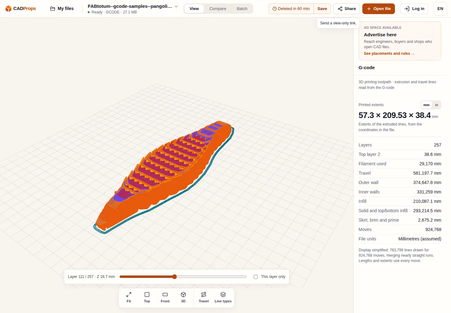
When the picture does not match the slicer
A line outside the main footprint may be a skirt, a brim or a travel move. Use the visible categories and the file order to distinguish them. Some slicers omit feature comments. If CADProps shows all extrusion in one colour, check the type in your slicer rather than assigning a meaning based on colour alone. Prints sliced one object at a time follow program order, so the layer numbers need not represent a single build-wide height sequence.
If the footprint still looks wrong, use the reference model overlay to check the source and its scale. These are programmed nozzle paths. The preview cannot tell you whether the filament will adhere to your bed or whether your printer's live Z offset is correct.
The screenshot uses FABtotum’s pangolin sample under CC0 1.0.
Original article: CADProps · https://www.cadprops.com/guides/gcode-first-layer-preview/