

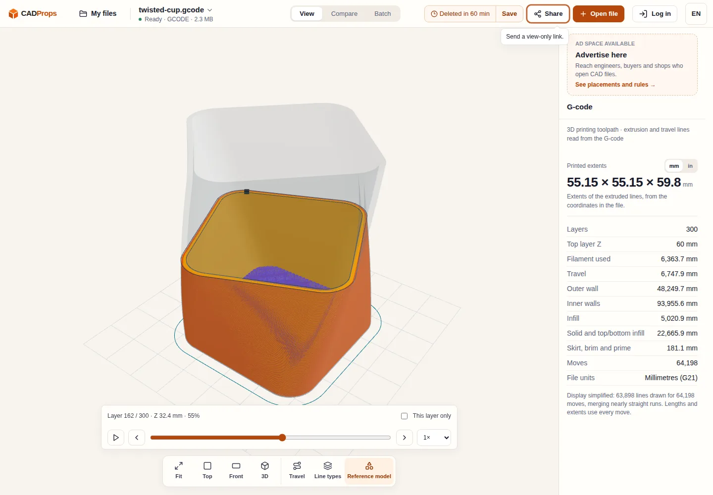
The toolpath looks like the part, but it sits off to one side. Before posting the job again, check that the program and model came from the same revision and that you are comparing them at the same origin. The CADProps G-code viewer can show both in the same view.
Add the source model and check placement
- Open the G-code program. Choose Reference model → Choose model, then select the model you sliced or used in CAM.
- Open Placement. For a print, start with the model on the bed and centred on the printed extents. For CNC, compare the suggested placement with the work origin set in CAM. CADProps places the model using its bounding box.
- Check Top and Front. Confirm a known span before adjusting position. If the origin is the only difference, enter the known offsets in Move model (mm). Changing the placement preset resets those offsets.
- Pause playback at a distinctive feature. Use Cut at the current layer or Cut at the current Z step to see the outline at that height. Turn the cut off when you need to see the whole part.
Read the kind of mismatch
| What you see | What to check |
|---|---|
| Same shape and size, shifted in one direction | Compare the slicer origin or CAM work origin with the model placement. |
| One view looks aligned but the other does not | Check the Z origin and the reference model orientation. |
| The outlines differ by roughly a factor of 25.4 | Check the program units and the units assumed for the model. STL and OBJ are read as millimetres. |
| A local feature is missing or in a different position | Confirm the file pair and revision before moving the overlay. |
In a print, the line marks the nozzle centre. A CNC outside profile follows the cutter centre, so its line can sit outside the part by the tool radius. A small offset can be expected. An overlay helps you identify where to investigate, but it cannot establish fixture clearance or verify the material removed by a cutter. See what the G-code viewer reads.
Original article: CADProps · https://www.cadprops.com/guides/compare-gcode-toolpath-to-cad-model/