
Open your file in the CADProps STEP viewer, choose Measure → Point coordinates, and click the corner you want to locate. The saved Point reading gives X, Y and Z relative to the STEP file's original axes. Check the displayed units before comparing the readings with a drawing or another export.
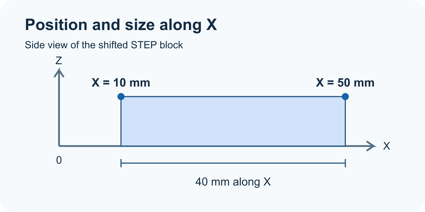
Try a block that starts 10 mm from the origin
- Download the shifted STEP block and open it in the viewer. Use millimetres and turn the model until the top corners are clear.
- Choose Point coordinates and select the top corner at the positive end of all three axes. That vertex is at (50, 30, 20) mm.
- Read the other end of the same top edge along X. The corresponding corner is at (10, 30, 20) mm. Subtracting the X readings gives the block's 40 mm length. The 10 mm offset is part of the model's placement.
If the point reads somewhere else
Zoom in and rotate to expose the corner, then select it again. A click near a mesh vertex can snap to that vertex. A click on the middle of a face can return a different location. Check a second known corner before using the coordinates in a handoff.
Fitting or rotating the view does not change the file axes. If the coordinates still disagree with a drawing, check whether that drawing uses a local datum or a different export origin. For a curved hole, the point tool reads the picked surface location. Use the supported measurement modes when your reference is a feature center or an axis.
Original article: CADProps · https://www.cadprops.com/guides/read-point-coordinates-step/