

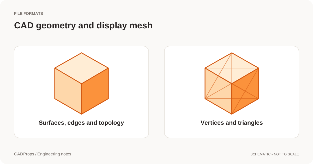
A valve block can look identical from the outside whether a cross-drilled passage meets the main bore or stops short. Open the STEP in the CADProps STEP viewer and use Section to clip away the material that blocks your view. Move the cutting plane through the area of interest before drawing a conclusion from what you see at one position.
Position the plane through the passage
- Confirm the model and its scale against the drawing. On an assembly, check in Structure which body you are looking at.
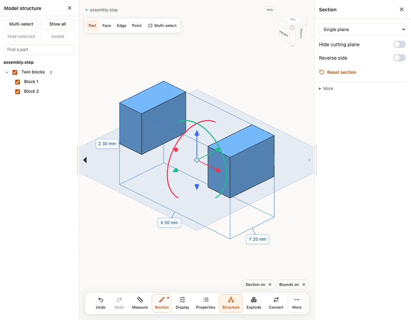
- Open Section and start with one plane. Drag the arrows to move it and the rings to rotate it. Aim the plane along the main bore, then move it across the suspected junction.
- If the cut hides the passage you wanted to retain, use Reverse side. Hide the plane graphic if it covers the area you are inspecting.
- After inspection, use Reset section to restore the unclipped view.
Move the cut before calling a passage blocked
In the valve-block example, an off-center cut might reveal the main bore while passing beside the cross-hole. That can make the hole look blocked. Move the plane a little in either direction and rotate the model to see the junction from both sides. If the passage appears only after moving the plane, record the view that actually exposes it.
A section is a visual check of the model you received. When a dimension matters, select the original cylindrical wall or circular edge with Hole / circle where the STEP supplies supported CAD geometry. For a location or spacing check, use the measurement mode that matches the drawing. The cut itself does not supply a section-area measurement or a new edge to use as design geometry. STEP measurement guide
If you need to send evidence to a colleague, include the model revision and identify the bore or face in the image. Sectioning changes the display while leaving the original geometry available for export.
Original article: CADProps · https://www.cadprops.com/guides/step-section-view-internal-passage/