
If a model looks heavier on one side, its bounding box alone cannot tell you where the material balances. Open the file in the CADProps STEP viewer and turn on Display → Center of mass. When the viewer can calculate a point, the panel lists its X, Y and Z coordinates in the selected display units and places a marker on the model.
Check the marker on a known STEP block
- Download the public block.step and open it in the viewer.
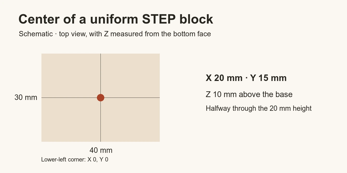
- In Properties, choose millimetres and confirm the bounding box is 40 × 30 × 20 mm.
- Open Display, find Center of mass and turn it on. Read the coordinates below the switch. For this sample, expect X 20, Y 15, Z 10 mm. The block starts at the origin, so the center is halfway along each side.
- Rotate the model to see the point from another angle. Use the displayed coordinates when you need to record the location.
Read the result for your own model
The viewer estimates the center from the display mesh using uniform density. On a bracket with an off-center cutout, the marker can shift toward the side with more material. The center of its bounding box still sits halfway between the outermost coordinates. Set rotation center is a separate camera control and can be moved to a convenient inspection point.
For an assembly with parts made of different materials, verify the balance in the authoring CAD system using the actual densities and a complete model. The marker in CADProps is a quick geometry check. It does not provide a verified lifting or fixturing point.
If the marker is unavailable
If the panel says the display mesh encloses no volume, check whether the file contains open surfaces or incomplete geometry. Try the public block in the same workspace to confirm what the control looks like when it has a result. For your own part, ask for a STEP export with closed solids when a usable balance estimate is needed.
Original article: CADProps · https://www.cadprops.com/guides/find-center-of-mass-step/